Field Remedy: 2021
| Subject: |
M20/M32 Transmission - Inexact shifting
and/or scraping noise during shifting from 3rd into 4th gear |
| Models: |
Engines: |
Option: |
| Vectra-C 2005...,Astra-H 2004...,Signum
2005...,Meriva 2006...,Corsa-D 2007...,Zafira-B 2005... |
Z22YH| Z19DTL| Z19DT,Z16LET| Z20LEL| Z20LEH|
Z20LER| Z13DTH| Z17DTH| Z19DT| Z19DTL| Z19DTH,Z22YH| Z19DTL|
Z19DT,Z16LET,Z13DTH| Z16LER,Z20LER| Z20LEH| Z22YH| Z19DT| Z19DTL|
Z19DTH |
M20-6/M32-6 speed transmission |
| Complaint: |
Inexact shifting and/or scraping noise
during shifting from 3rd into 4th gear. |
| Cause: |
Defective synchroniser ring 3rd and 4th
gear. |
| Production: |
Several improvements have been introduced in
production as of the following transmission-No: A 50270156
(24.11.2005). |
Remedy:
Note:
The TSB 2021 can only be used for transmissions up to
transmission number: A 02058820 (04 February 2010).
Note:
Only M20-6/M32-6 speed transmission affected,
not F40-6 speed transmission.
In case of customer complaint the transmission has to be checked as
discribed below.
Install repair kit manual transmission if necessary.
Spare-Parts: Part-No.: Catalogue-No.:
Seal remover Loctite 7200
(order at your local Loctite retailer)
Note:
The usage of Loctite 7200 is mandatory.
Repair kit manual transmission 93189976 90 07 192
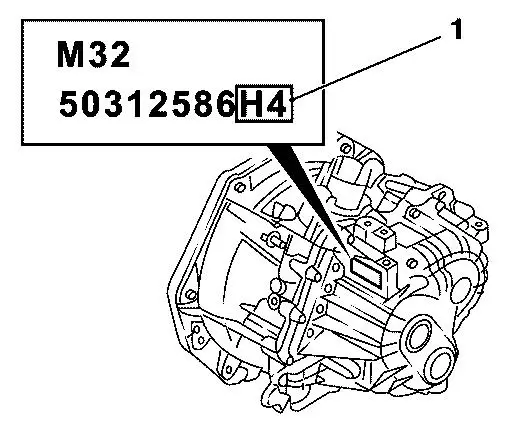
identification marks:
NU, NS, J3, J4, J5, J8,
J9, NR, C8, D4, H3, H4,
G9, F6, GK, YP, YQ, XA
YU, YA, YT, YH, YB, YD
Repair kit manual transmission          93189977       90 07 193
identification marks:
C6, C7, D3, D5, D7, D8,
D9, E1, G7, G8, GJ, H1,
H2, YG, YE, YF, YL, YK
YN, YJ, YM
Transmission oil (1 liter) 9120541 19 40 768
Transmission oil (60 liter) 9194349 19 40 710
Locking compound 90542117 15 10 181
Transmission oil drain bolt 93180976 7 02 929
Transmission oil filler bolt 90446270 7 02 219
Sealing compound 90297970 15 03 167
Order repair kit manual transmission according to identification mark
on identification plate of transmission (position 1 in picture below).
Working Procedure:
1. Remove transmission
    - see working procedure "Transmission, Remove and Install" ,
      group "K" according service literature.
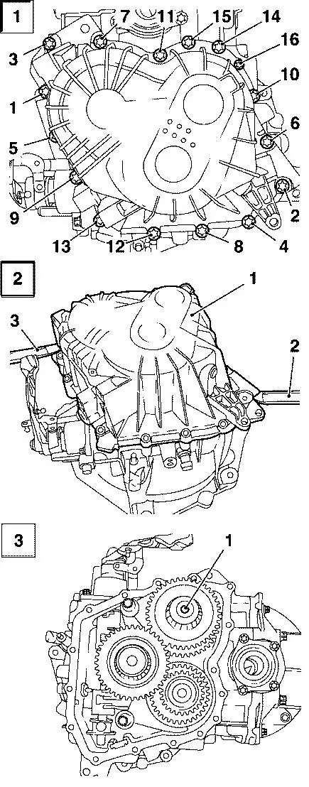
2. Loose transmission housing cover (Picture 1).
- remove 16x screw
3. Remove transmission housing cover (1) (Picture 2).
- lift up constant with adequate tool (2) and (3)
    Note:
    No thumping or striking.
    Note:
    3rd and 4th gear are mounted on top of primary shaft
    (1, Picture 3).
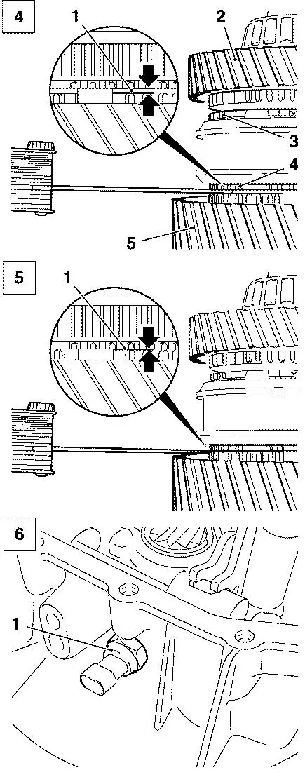
4. Check gap clearance of 3rd gear.
    Note:
    2nd technician necessary.
    - engage 4th gear
    - push synchronising disk in direction of 3rd gear
    - check gap clearance between synchronising disk
      3rd gear (4, Picture 4) and gear wheel of
      3rd gear (5, Picture 4)
5. Check gap clearance of 4th gear.
    Note:
    2nd technician necessary.
    - engage 3rd gear
    - push synchronising disk in direction of 4th gear
    - check gap clearance between synchronising disk
      4th gear (3, Picture 4) and gear wheel of
      4th gear (2, Picture 4)
    Important:
    Clearance between synchronising disk and gear wheel
< 1 mm      (1, Picture 5)- synchronising disk worn out, repair necessary.     Clearance between synchronising disk and gear wheel >
= 1 mm
    (1, Picture 4)- syncronising disk ok.
    Install the complete repair kit with synchronising disks
    and gear wheels 3rd and 4th gear if one of both
    synchronising disks is worn out.
Measurement OK (Picture 4)
    Note:
    Picture 4 shows the measurement of clearance of 3rd gear.
    Act accordingly to measure the clearance of 4th gear.
Measurement NOK (Picture 5)
    Important:
    Install the complete repair kit with synchronising disks
    and gear wheels 3rd and 4th gear if one of both
    synchronising disks is worn out.
6. Remove reverse lamp switch (1, Picture 6).
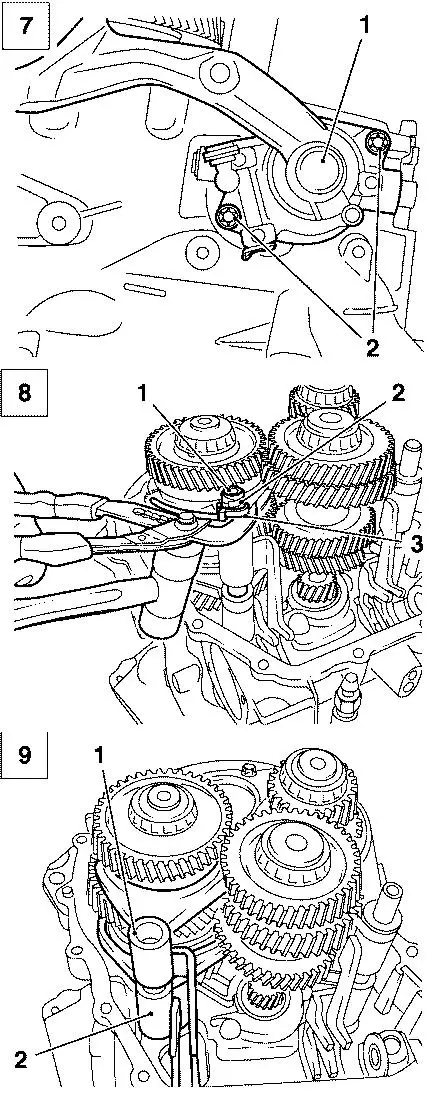
7. Remove gear shift assembly (1, Picture 7).
    - engage neutral gear
    - remove 2x screw (2)
8. Remove control rod (1) of primary shaft (Picture 8).
    - degrease control rod
    - wrap adhesive tape (2) several times around control rod
    - attach cable strap (3) to prevent control rod from sliding
      down
    - grab adhesive tape with gripper
    - strike out control rod vertical bottom-up
    Important:
    Do not damage control rod.
9. Remove 2x selector fork (Picture 9).
    Note:
    In case of any damages on the sliding shoes of the shift fork
    3./4. gear (1)(Picture 9), use a new reinforced shift fork
    (Partnumber: 55570787 / Cataloguenumber: 7 34 000) when assembling
    the transmission.
- from reverse gear (2) and 3rd/4th gear (1)
10. Remove top primary shaft (1, Picture 10).
    - grab primary shaft at 3rd gear wheel and remove it
      from transmission housing
11. Remove retaining ring of taper roller bearing (1, Picture 11).
    Important:
    Keep retaining ring. The thickness of the retainer ring must
    be measured later.
12. Press-out taper roller bearing (2) (Picture 12).
- prop at 4th gear wheel (3)
    Important:
    taper roller bearing must be re-used.
    The transmission has to be replaced if the taper roller
    bearing gets damaged.
    Note:
    Diameter of mandril (1) max. 24mm.
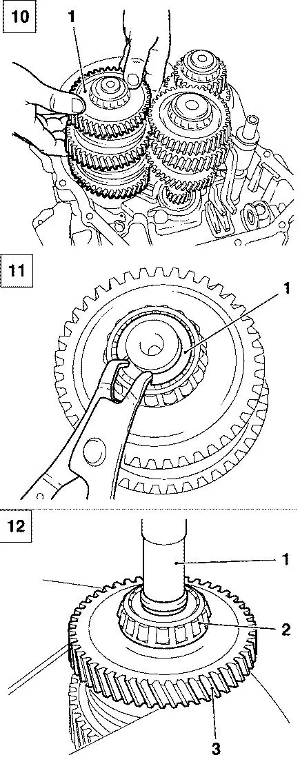
13. Remove needle bearing 4th gear (1) and synchronising disks (2)
    (Picture 13).
14. Remove retaining ring (1) from sleeve carrier (2) (Picture 14).
15. Press-off sleeve carrier (1, Picture 15).
- apply pressure to gear wheel of 3rd gear (2)
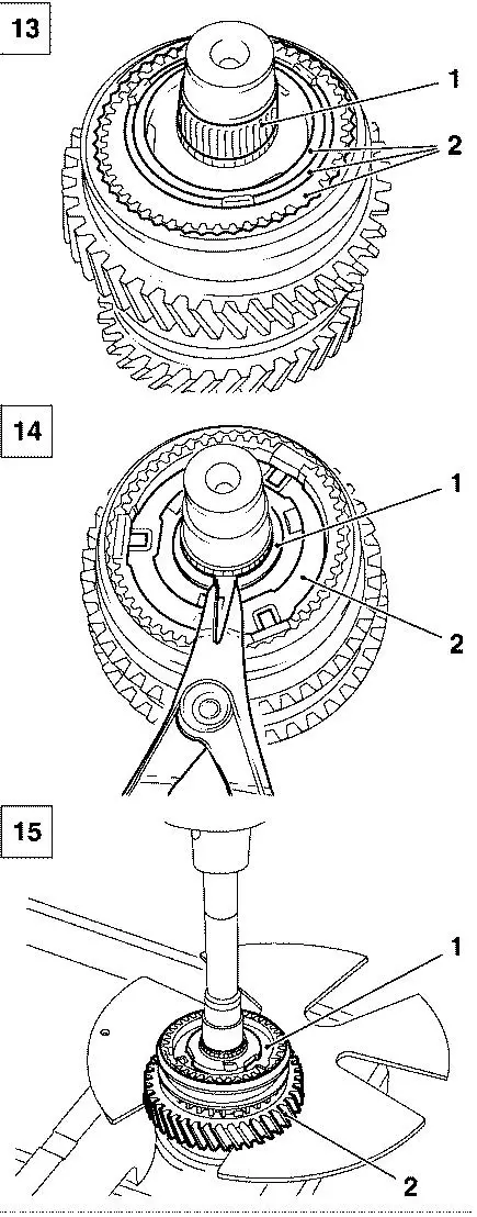
16. Remove needle bearing 3rd gear (1, Picture 16).
17. Remove retaining ring of distance bush (1, Picture 17).
    Important:
    Do not damage bearing face of 3rd gear.
18. Press-off distance bush (1) (Picture 18).
- use KM-6223-1 (3) and KM-6223-2 (2)
19. Align and press-on new distance bush (2) (Picture 19).
- press on block with provided bushing (1)
20. Install new retaining ring (1, Picture 17).
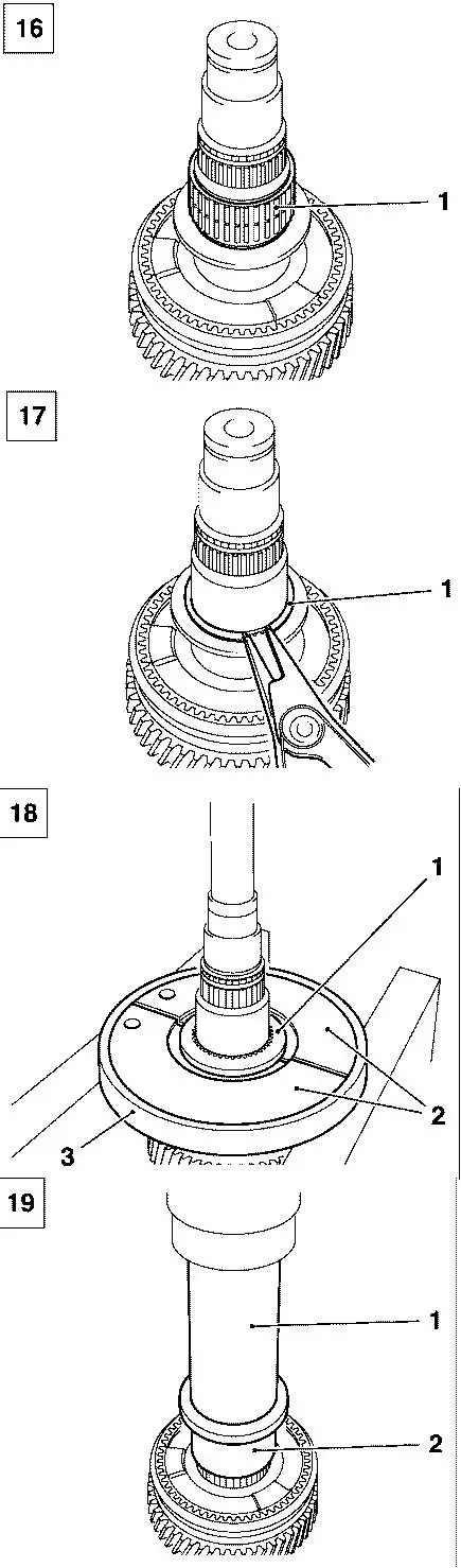
21. Install new gear wheel 3rd gear (3) (Picture 20)
    with needle bearing (see pos.1 in Picture 16).
    Note:
    Take care of needle bearing.
22. Install new synchronising disks (packet of 3) (2) (Picture 20).
- spin gear wheel after pressing
    Note:
    Observe alignment of synchronising disks:
    Place lugs (1) of gear wheel and synchronising
    disk (1) congruent.
23. Mark and dissasemble new sleeve carrier with selector
    sleeve (1) (Picture 21).
    Important:
    Sleeve carrier and selector sleeve must be installed later
    in the same setting.
24. Align and press-on new sleeve carrier (2) (Picture 22).
- press on block with provided bushing (1)
    Note:
    Observe alignment of apertures (3) to synchronising disk.
25. Install new retainer ring (4) and new selector sleeve (3)
    (Picture 23).
    Note:
    Regard mark (2).
    - place selector sleeve
    - install 3x thrust piece (1)
    - affix 3x thrust piece angular
    - press-in 3x thrust piece
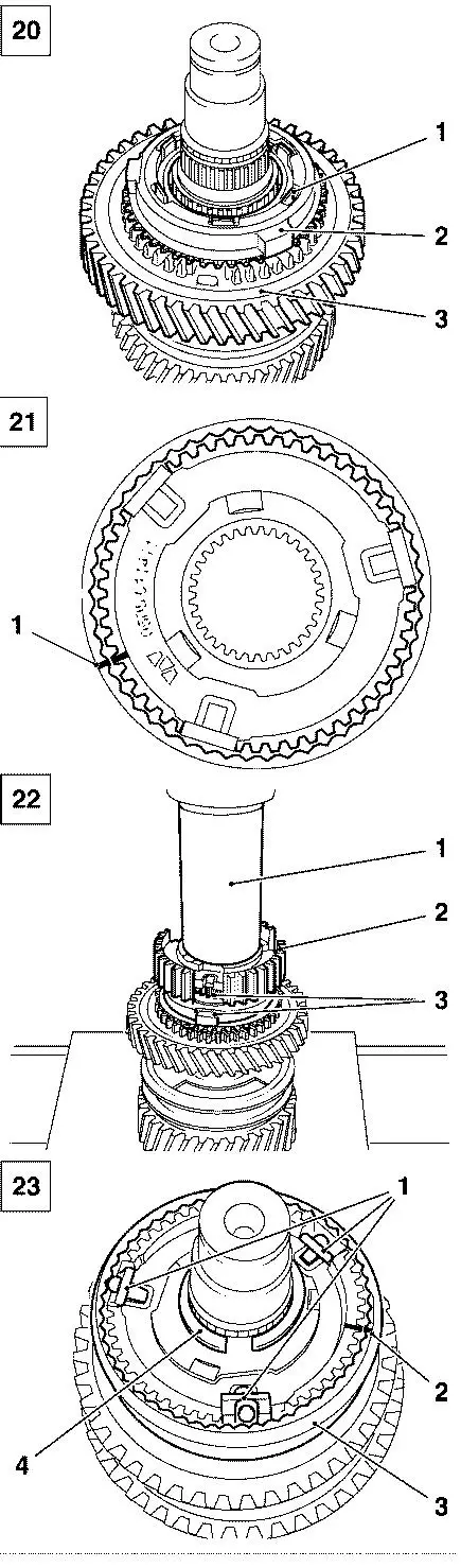
26. Functional check 3rd gear.
    - spin gear wheel 3rd gear
    Note:
    Test: fast spinning – slight backlash.
    A little resistance is normal.
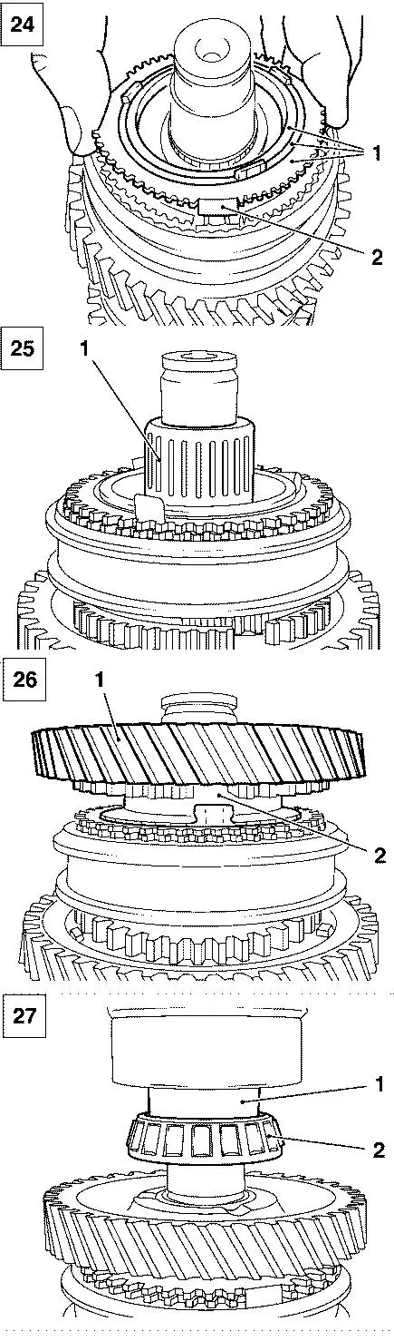
27. Install and catch new synchronising disks (packet of 3) (1)
    (Picture 24).
    Note:
    Pay attention to aperture (2).
28. Install new needle bearing 4th gear (1, Picture 25).
29. Install new gear wheel 4th gear (1) (Picture 26).
- engage lugs (2)
30. Functional check 4th gear.
- spin gear wheel 4th gear
    Note:
    Test: fast spinning – slight backlash.
    A little resistance is normal.
31. Press-on old taper roller bearing (2) in correct
    position (Picture 27).
- use provided bushing (1)
32. Install new retainer ring (see position 1 in Picture 11).
    Important:
    The retaining rings have classified thicknesses.
    Measure thickness of old retaining ring in an area without
    burr.
    Install new retainer ring out of provided set with identical
    thickness.
33. Spray seal faces of transmission housing and
    transmission housing cover with seal remover Loctite 7200.
- Let seal remover permeate for 15 minutes
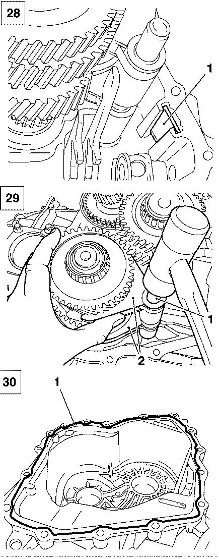
34. Clean magnet in transmission (1, Picture 28)
35. Clean 16x thread in transmission housing
    - cover gear wheels
    - blow threads with compressed air after cleaning with
      tapper
36. Insert primary shaft on top (see position 1 in Picture 10).
37. Insert 2x selector fork
- reverse gear (2) and 3rd/4th gear (1)
    Note:
    See picture 9.
38. Install control rod (1, Picture 29)
    - remove adhesive tape and cable strap from control rod
    - assemble in control rod with plastic hammer
    Note:
    Assure that selector forks lie against selector sleeve
    while assembling control rod.
    Avoid canting of control rod.
39. Install gear shift assembly (see position 1 in picture 7).
- tighten 2x screw (2) with 21 Nm
40. Install reverse lamp switch (see position 1 in picture 6).
- tightening torque 20 Nm
41. Clean sealing  surface of transmission housing and
    transmission housing cover.
- wipe off seal remover with clean rag
42. Apply sealing compound Loctite 518 (1) to transmission
    housing cover uninterrupted with 2-3 mm thickness
    (Picture 30).
43. Mount transmission housing cover (see picture 1)
    Note:
    Tighten screws as shown in picture 1
    - tighten 16x screw
    - 1st step: 5 Nm
    - 2nd step: 21 Nm
    - check for correctness :
      retighten all screws clockwise with 21 Nm
    Note:
    Screw 16 has to be installed in its original position
    (see position 16 in picture 1)
44. Functional check before installation.
    - shift each gear and rotate transmission at input shaft
      , mount clutch plate.
45. Install transmission
    - see working procedure "Transmission, Remove and Install ",
      group "K" of according service literature.
Labour Times: TC: Hours:
    Note:
    All labour times are containing required time for removal and
    installation of transmission and time for installation of repair
    kit manual transmission.
Astra-H - Z 16 LET/M32
U3 202 10      Install repair kit              90             6.2
               manual transmission
Astra-H - Z 20 LEL, Z 20 LEH, Z 20 LER/M32
U3 202 10      Install repair kit              90             6.1
               manual transmission
Astra-H - Z 13 DTH/M20
U3 202 10      Install repair kit              90             6.1
               manual transmission
Astra-H - Z 17 DTH/M32
U3 202 10      Install repair kit              90             7.1
               manual transmission
Astra-H - Z 19 DT, Z 19 DTL/M32
U3 202 10      Install repair kit              90             7.1
               manual transmission
Astra-H - Z 19 DTH/M32
U3 202 10      Install repair kit              90             7.1
               manual transmission
Zafira-B - Z 20 LER, Z 20 LEH/M32
U3 202 10      Install repair kit              90             5.8
               manual transmission
Zafira-B - Z 22 YH/M32
U3 202 10      Install repair kit              90             5.9
               manual transmission
Zafira-B - Z19 DT, Z 19 DTL, Z 19 DTH/M32
U3 202 10      Install repair kit              90             6.7
               manual transmission
Meriva - Z 16 LET/M32
U3 202 10      Install repair kit              90             5.4
               manual transmission
Vectra-C/Signum - Z 22 YH/M32
U3 202 10      Install repair kit              90             5.9
               manual transmission
Vectra-C/Signum - Z 19 DT, Z 19 DTL/M32
U3 202 10      Install repair kit              90             6.1
               manual transmission
Corsa-D - Z 16 LER/M32
U3 202 10      Install repair kit              90             5.4
               manual transmission
Corsa-D - Z 13 DTH/M20
U3 202 10      Install repair kit              90             5.5
               manual transmission
The costs for this repair will be covered during the normal warranty.
The regular warranty procedure will apply.
| FunctionalGroup: |
K - Clutch/Transmission |
| Complaint Group: |
08 - Hard to operate |
| Trouble Code: |
None |
|
