|
Replace steering gear (ZF)
| Spezialwerkzeugliste: |
- CH-47658
- KM-161-2
- KM-161-B
- KM-6004-2
- KM-J-22610
|
Note: Only front axle
body is released. The guide joints remain attached to the steering
knuckle.
 Remove Remove
| 1. |
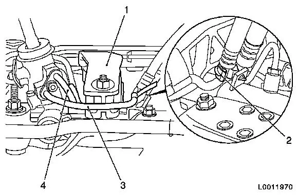
Turn steering wheel as far as the stop
| • |
Turn steering wheel and front wheels to the straight-ahead
position.
|
| • |
Allow steering lock to engage
|
|
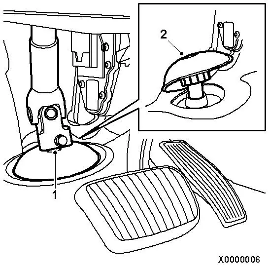
| 2. |
Remove intermediate shaft from steering gear.
| • |
Remove clamp bolt (1) of intermediate shaft.
Note: Bolt is
accessible from the passenger compartment.
|
| • |
Detach intermediate shaft from steering wheel.
|
|
| 3. |
Remove rubber sleeve from steering gear (2).
|
|
|
| 4. |
Detach 2x front wheels
| • |
Remove 10x wheel bolts
Note: Mark position
relative to the wheel hub.
|
|
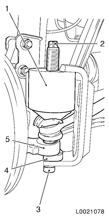
| 5. |
Release 2x tie rod ends (6) from steering knuckle (5)
| • |
Attach CH-47658 (1)
| – |
Place CH-47658 (1) in position with a
suitable sleeve (4)
Note: To centre CH-47658 , CH-47658
must be inserted with a suitable socket (3).
|
| – |
Fasten CH-47658 (1) to hex (2)
|
|
| • |
Unscrew tie rod end nut
|
|
|
|
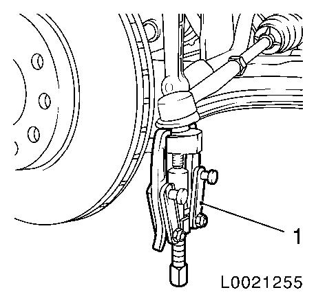
| 6. |
Detach 2x tie rod ends from steering knuckle
| • |
Press tie rod end out of steering knuckle using KM-161-B (1) combined with KM-161-2
|
|
|
|
| 7. |
Detach lower engine compartment cover
|
|
|
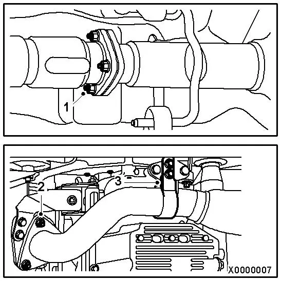
| 8. |
Remove front exhaust pipe.
| • |
Remove 3 nuts for connecting the front pipe to the particle
filter / rear catalytic converter (1).
|
| • |
Remove 3 nuts for connecting the pipe to the front catalytic
converter (2).
|
| • |
Remove the bracket from the oil pan (3).
|
| • |
Remove the exhaust pipe.
Note: The flexible part
of the pipe must not be bent by more than 5°.
|
|
|
|
| 9. |
Remove rear engine damping block from transmission.
|
|
|
| 10. |
Place vehicle jack in position under the front axle
housing.
|
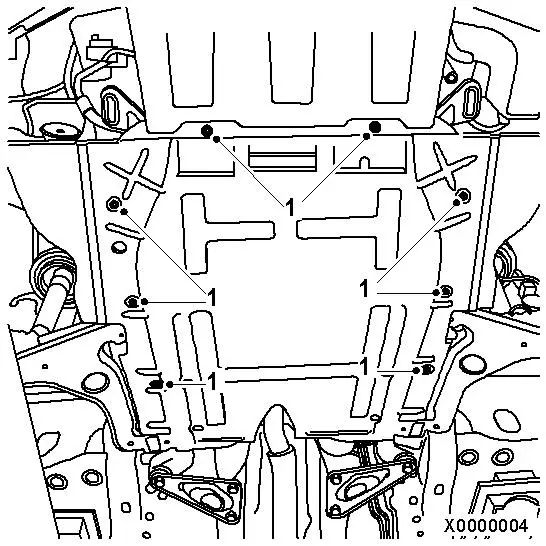
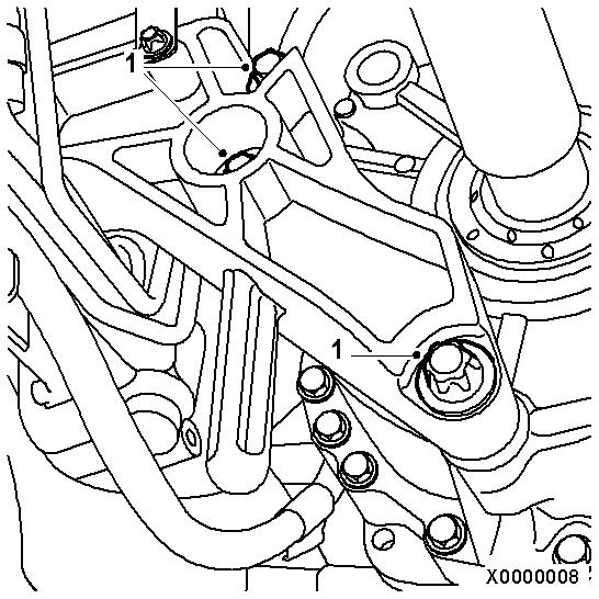
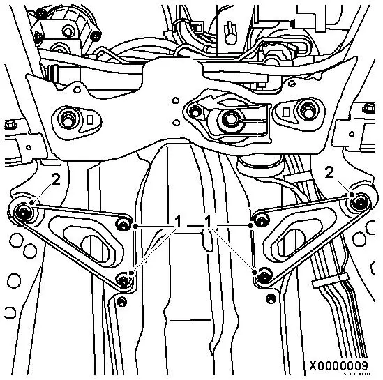
| 11. |
Remove triangular plate.
| • |
Unscrew 6 bolts (1) (2).
|
|
|
|
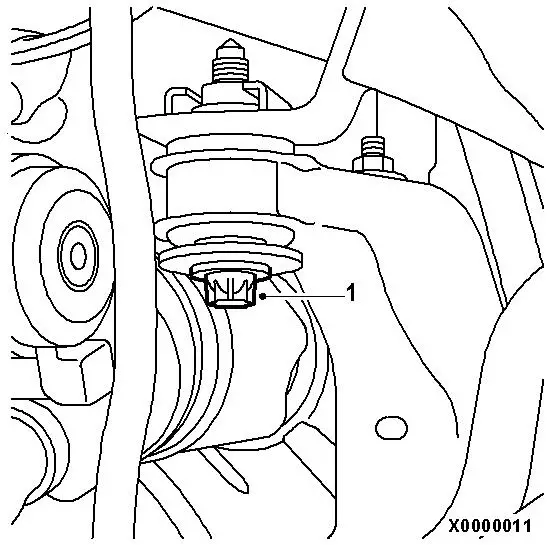
| 12. |
Remove centre bolts from axle housing (1) 2x.
|
|
|
|
| 13. |
On LHD vehicles: Remove engine damping block bracket (1) at the
rear of engine damping block.
|
| 14. |
Detach rear engine damping block (2)
Note: Illustration
shows front axle body removed.
| • |
Unscrew bolt connection
|
|
| 15. |
Remove supply line (3) and return line (4) from steering
gear
Note: Oil runs out -
use catchment tray
|
|
|
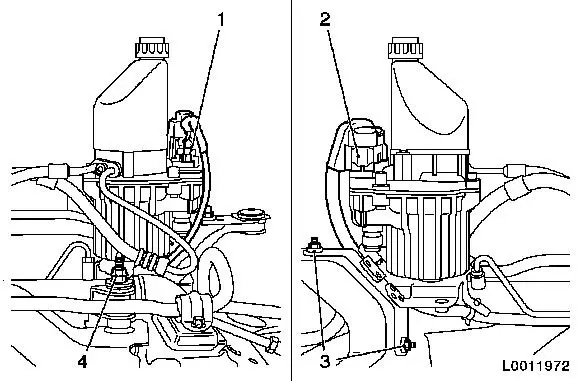
| 16. |
Remove electro-hydraulic supply unit from front axle body
| • |
Release 2x wiring harness plug (1) and (2) and remove from
electro-hydraulic supply unit
|
| • |
Remove 3x nuts (3) and (4) from steering gear and front axle
body
|
| • |
Remove electro-hydraulic supply unit with supply and return
line from steering gear and front axle body
|
|
|
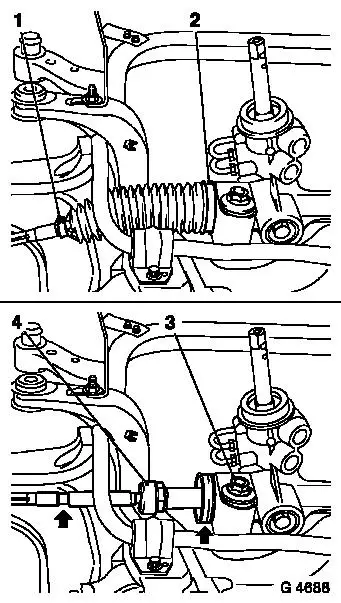
| 17. |
Remove tie rods on both sides of steering gear
| • |
Detach 2x retaining strap (1) and (2)
|
| • |
Remove 2x boot from steering gear
|
| • |
Detach 2x tie rod (4) from steering gear with KM-6004-2
| – |
counterhold with an open-ended wrench on the toothed rack flat
on the steering shaft side
Note: Counterholding is
no longer necessary in vehicles as of model year 2006.
|
|
|
| 18. |
Remove steering gear from front axle body
| • |
Remove 2x nut (2) from front axle body
|
|
|
|
 Install
| 19. |
Attach steering gear to front axle body
| • |
Tighten 2x new nuts 45 Nm + 45° +
15°
|
|
| 20. |
Attach 2x tie rod to steering gear with KM-6004-2 90 Nm
Note: Clean thread on
rack and coat with locking compound.
| • |
counterhold with an open-ended wrench on the toothed rack flat
on the steering shaft side
Note: Counterholding is
no longer necessary in vehicles as of model year 2006.
|
|
| 21. |
Attach 2x boot to steering gear
| • |
Place 2x boot on steering gear
Note: Ensure that the
boot sits in the grooves of the tie rod and steering gear
|
| • |
Attach 2x new retaining clamp to steering gear with KM-J-22610
|
| • |
Fit 2x boot to tie rod using new retaining strap
Note: Ensure that the
boots sit in the grooves of the tie rod.
|
|
| 22. |
Attach electro-hydraulic supply unit with bracket to front axle
body 22 Nm
| • |
Place electro-hydraulic supply unit with holder on steering
gear and front axle body
Note: Note steering
wiring harness
|
|
| 23. |
Connect 2x wiring harness plug to electro-hydraulic supply
unit
|
| 24. |
Attach supply and return line to steering gear 16 Nm
|
| 25. |
Attach supply and return line holder to steering gear
|
| 26. |
Attach rear engine damping block bracket to engine damping
block 55 Nm
|
| 27. |
Fit bolts for front axle housing.
| • |
Fit triangular plates, insert the following new bolts and leave
slack.
| – |
Tighten 2x bolts (2) for front axle housing to 90 Nm +45° +15° .
|
| – |
Tighten 4x bolts (1) for triangular plates to vehicle underbody
65 Nm
|
|
|
|
|
| 28. |
Insert centre bolts for front axle body and leave slack
| • |
Tighten 2x bolts for front axle housing (1) to 90 Nm +45° +15° .
|
|
|
|
| 30. |
Place engine support underneath, at the back on the
transmission.
| • |
Tighten bolt to 80 nm .
|
|
| 31. |
Attach front exhaust pipe.
| • |
Lubricate the bolts with bolt paste and fit the pipe between
the front and rear catalytic converter.
Note: Use new gaskets
and new nuts. Tighten to 25 nm .
Note: The flexible part
of the pipe must not be bent by more than 5°.
|
| • |
Fit bracket to oil pan and tighten the bolts to 25 Nm .
|
|
| 32. |
Attach lower engine compartment cover.
| • |
Tighten 8x bolts to 5 Nm .
|
|
| 33. |
Charge and bleed hydraulic system 
|
| 34. |
Check straight-ahead position, adjust if necessary
|
| 35. |
Check toe-in, adjust if necessary
|
| 36. |
Attach front wheels
| • |
Tighten 10x wheel bolts 110 Nm
|
|
|
