Liftgate Window Replacement (5-Door Wagon 35)
Special Tools
| • |
BO-46974 Glass
Removal System |
For equivalent regional tools, refer to
Special Tools .
For needed amount of one part adhesive, refer to
Adhesives, Fluids, Lubricants, and Sealers .
Removal Procedure
Warning: Refer to
Cracked Window Warning .
Warning: Refer to
Glass and Sheet Metal Handling
Warning .
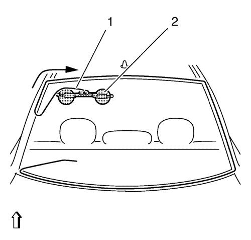
Note: Position the vehicle
on level ground and move the front wheels to the straight-ahead
position
| 4. |
Disconnect the liftgate window
radio antenna connector. |
| 5. |
Disconnect the electrical
connectors from the liftgate window defogger bus bars. |
| 6. |
Cover the following parts to
protect from the broken glass: |
| 7. |
Use BO-46974
system to remove the liftgate window. |
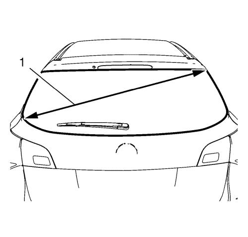
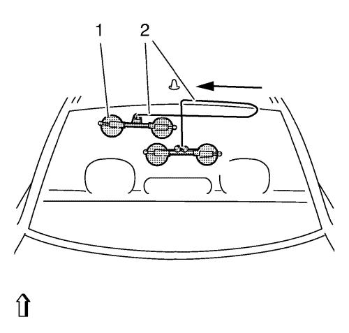
| 8. |
Take the diagonal measurement
(1) of the liftgate window. |
| 9. |
Cut cutting wire into four
times lengths. |
| |
Approximately 5400 mm (212.597 in), the circumference of the
corresponding roll of wire is approximately 1000 mm (39.369
in). |
| 10. |
Heat the awl with a suitable
tool. |
|
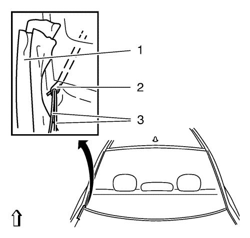
Note: Ensure that the
liftgate window is not damaged in the process. Otherwise, stress
cracks could form in the liftgate window. Mask off the area with
fabric tape (1).
|
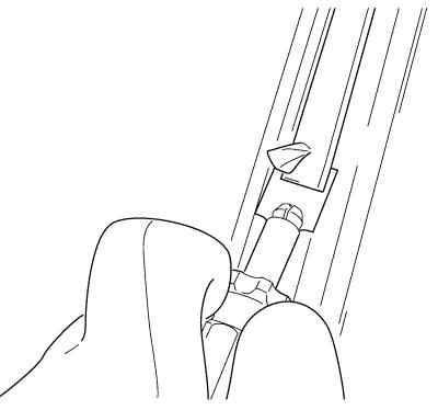
| 11. |
Stick the awl (2) through the
adhesive bed in the area of the lower C-pillar. |
| 12. |
Pull the wire through.
|
| |
• |
Thread both ends of the
cutting wire (3) in the bores of the piercing awl (2) and bend
them. |
| |
• |
Use the piercing awl (2) to
pull the cutting wire to the centre of the liftgate window.
|
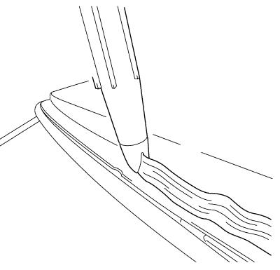
|
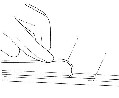
Note: The cutting
wire (1) should be rolled in beneath the rubber window seal (2) at
the liftgate window.
|
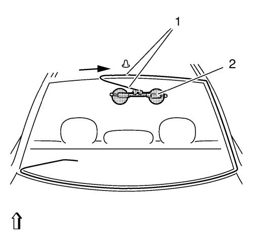
| 13. |
Lay the wire (1) under the
liftgate window all the way round. |
| 14. |
Pull the remaining wire into
the interior. |
|
Note: Ensure that the
cutting wire is fitted correctly to the winch deflection
roller.
|
| 15. |
Place the winch with two
winding heads on liftgate window inside. |
| |
• |
Position the winch vertically
at the same height as the C-pillar. |
| |
• |
Attach the cutting wire to the
winch (1). |
| |
• |
Insert transfer ratchet and
pre-tension cutting wire. |
|
Note: Arrow shows the
path taken by the cutting wire.
|
| 16. |
Cut out the liftgate window
until the cutting wire is level with the winch. |
|
Note: Ensure that the
cutting wire is fitted correctly to the winch deflection
roller.
|
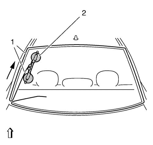
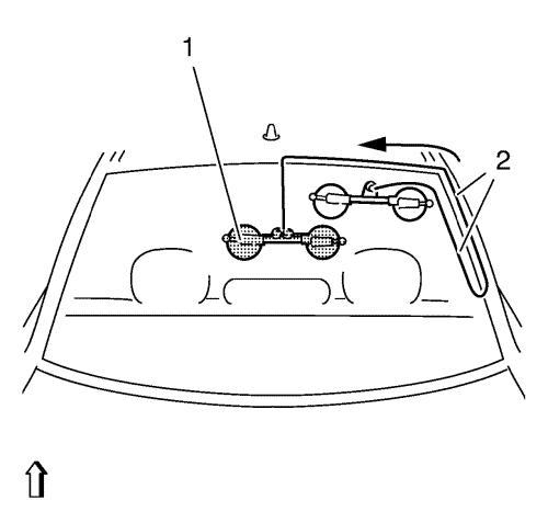
| 17. |
Place the winch with two
winding heads in the vehicle. |
| |
• |
Position the winch (2) in the
area of the roof frame. |
| |
• |
Insert transfer ratchet and
pre-tension cutting wire (1). |
|
Note: Arrow shows the
path taken by the cutting wire.
|
|
Note: Increased
cutting effort is required in the area of the liftgate window
radius.
|
| 18. |
Cut out the liftgate window
until the cutting wire is level with the winch. |
|
Note: Ensure that the
cutting wire is laid correctly to the winch deflection roller.
|
| 19. |
Place the winch with two
winding heads in the vehicle. |
| |
• |
Position winch in the middle
area of liftgate window (2). |
| |
• |
Insert transfer ratchet and
pre-tension cutting wire (1). |
|
Note: Arrow shows the
path taken by the cutting wire.
|
| 20. |
Cut out the liftgate window
until the cutting wire is level with the winch. |
|
Note: Ensure that the
cutting wire is fitted correctly to the winch deflection
roller.
|
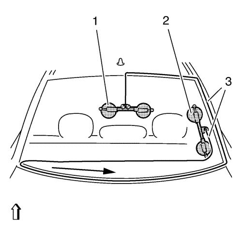
| 21. |
Position the winch with one
winding head on liftgate window inside. |
| |
• |
The winch with 2 winding heads
(1) stays in the position. |
| |
• |
Position winch with one
winding head (2) in the area of the lower C-pillar. |
| |
• |
Thread the second end of the
wire (3). |
| |
• |
Insert transfer ratchet and
pre-tension cutting wire. |
|
Note: Arrow shows the
path taken by the cutting wire.
|
|
Note: Increased
cutting effort is required in the area of the liftgate window
radius.
|
| 22. |
Cut out the liftgate window
until the cutting wire is level with the winch. |
|
Note: Check that the
cutting wire is laid correctly at the winch deflection roller.
|
| 23. |
Position the winch with one
winding head in the vehicle. |
| |
• |
Position the winch with one
winding head (1) in the upper area of the liftgate window.
|
| |
• |
Insert transfer ratchet and
pre-tension cutting wire (2). |
|
Note: Arrow shows the
path taken by the cutting wire.
|
|
Note: Increased
cutting effort is required in the area of the liftgate window
radius.
|
| 24. |
Cut out the liftgate window
until the cutting wire is level with the winch. |
|
Note: Check that the
cutting wire is laid correctly to the winch deflection roller.
|
| 25. |
Position the winch with one
winding head on liftgate window inside. |
| |
• |
Position winch with one
winding head (1) next to winch with two winding heads so that the
cutting wire crosses (2). |
| |
• |
Insert transfer ratchet and
pre-tension cutting wire. |
|
Note: Arrow shows the
path taken by the cutting wire.
|
| 26. |
Cut out the liftgate window
until the cutting wire (2) has cut through the adhesive bead
completely. |
| 27. |
Remove glass removal
system. |
| 28. |
Fit and lock BO-641
holder onto liftgate window. |
|
Note: Second
technician required.
|
| 29. |
Remove liftgate window.
|
| 30. |
Cut out the adhesive tape with
the knife provided (1) to within 1 mm (0.039 in). |
| 31. |
Repair any paint
damage. |
| |
Using a touch-up pen to match the color of the vehicle, repair
any paint damage. |
| 32. |
If the liftgate window rubber
is damaged, replace with a new one. |
| 33. |
Cut off the adhesive bead on
the glass pane. |
| |
Cut out the adhesive tape with the knife provided to within 1
mm (0.039 in). |
Installation Procedure
| 1. |
Remove all mounds or loose
pieces of urethane adhesive from the pinch-weld area. |
| 2. |
Inspect for any of the
following conditions in order to help prevent future breakage of
the window: |
| |
• |
Any other obstruction or
irregularity in the pinch-weld flange |
| 3. |
After repairing the opening as
indicated, perform the following steps: |
| |
Remove all traces of broken glass from the outer cowl panel,
seats and floor. |
| 4. |
Apply adhesive bead
(1). |
| |
Cut into the tip of the cartridge in such a way that a bead of
adhesive approx. 13 mm (0.511 in) thick is produced. |
| 5. |
Insert liftgate window.
|
| |
• |
Place the liftgate window at
the upper area and lower down. |
|
Note: Second technician
required.
|
| |
|
|
| |
• |
Insert liftgate window with
BO-641 holder . |
| 6. |
Secure liftgate window in
position with fabric tape. |
| 7. |
Clean any excess urethane
adhesive from the body. |
| 8. |
Use a soft spray of warm water
in order to immediately water test the window. |
| 10. |
If any leaks are found, use a
plastic paddle in order to apply extra urethane adhesive at the
leak point. |
| 11. |
Retest the window for
leaks. |
| 12. |
Maintain the following
conditions in order to properly cure the urethane adhesive:
|
| |
• |
Partially lower a door window
in order to prevent pressure buildups when closing doors before the
urethane adhesive cures. |
| |
• |
Do not drive the vehicle until
the urethane adhesive is cured. Refer to the above curing
times. |
| |
• |
Do not use compressed air in
order to dry the urethane adhesive. |
| 13. |
Connect the electrical
connectors to the liftgate window defogger bus bars. |
| 14. |
Connect the liftgate window
radio antenna connector. |
|
