Front Brake Caliper Bracket Replacement (16 inch Brake
System)
Removal Procedure
| 1. |
Inspect the fluid level in the
brake master cylinder reservoir. |
| 2. |
If the brake fluid level is
midway between the maximum-full point and the minimum allowable
level, no brake fluid needs to be removed from the reservoir before
proceeding. |
| 3. |
If the brake fluid level is
higher than midway between the maximum-full point and the minimum
allowable level, remove brake fluid to the midway point before
proceeding. |
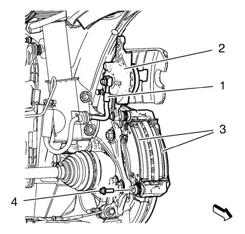
| 6. |
Remove the lower brake caliper
guide pin bolt (4). Do NOT disconnect the hydraulic brake flexible
hose (1) from the caliper (2). |
|
Caution: Support the brake caliper with heavy mechanic wire, or
equivalent, whenever it is separated from its mount and the
hydraulic flexible brake hose is still connected. Failure to
support the caliper in this manner will cause the flexible brake
hose to bear the weight of the caliper, which may cause damage to
the brake hose and in turn may cause a brake fluid leak.
|
| 7. |
Without disconnecting the
hydraulic brake flexible hose (1), pivot the caliper (2) upward and
separate from caliper bracket in direction of arrow. |
| 8. |
Remove the brake pads
(3). |
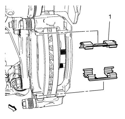
| 9. |
Remove the brake pad retainer
springs (1). |
| 10. |
If reusing the bracket,
thoroughly clean the pad hardware mating surfaces of the caliper
bracket, of any debris and corrosion. |
| 11. |
Inspect the brake pad retainer
springs (1) for the following: |
| |
• |
Looseness at the brake caliper
mounting bracket |
| |
• |
Looseness at the disc brake
pads |
| 12. |
If any of the conditions
listed are found, the disc brake pad retainers require
replacement. |
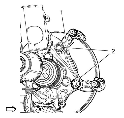
| 13. |
Remove and DISCARD caliper
bracket bolts (2). |
| 14. |
Remove brake caliper bracket
(1) from steering knuckle. |
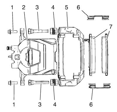
| 15. |
Inspect the caliper bracket
(5). If the brake caliper bracket (5) is bent, cracked, or damaged,
it requires replacement. |
| 16. |
Inspect the brake caliper
guide pins (3) for freedom of movement, and inspect the condition
of the guide pin boots (4). Move the brake caliper guide pins (3)
inboard and outboard within the brake caliper bracket (5), without
disengaging the slides from the boots (4), and observe for the
following: |
| |
• |
Restricted caliper guide pin
movement |
| |
• |
Looseness in the brake caliper
mounting bracket |
| |
• |
Seized or binding caliper
guide pins |
| 17. |
If any of the conditions
listed are found, the brake caliper guide pins (3) and/or boots (4)
require replacement. |
Installation Procedure
| 1. |
Install the brake caliper
bracket (1) to the steering knuckle. |
| 2. |
Install the NEW brake caliper
bracket bolts (2) and tighten a first pass to 150
N·m (111 lb ft) . |
| 3. |
Tighten the NEW brake caliper
bracket bolts a final pass to an additional 45 to 60
degrees . |
| 4. |
Apply a very thin coating of
high temperature silicone brake lubricant to the pad hardware
mating surfaces of the caliper bracket only. Refer to
Adhesives, Fluids, Lubricants, and Sealers for the recommended
lubricant. |
| 5. |
Install the brake pad retainer
springs (1). |
|
Note: The wear sensor
equipped disc brake pad must be mounted inboard of the rotor with
the leading edge of the sensor facing the brake rotor during
forward wheel rotation, or at the top of the pad when installed in
vehicle position.
|
| 6. |
Install the brake pad
retainers (3) to the brake caliper bracket. |
| 7. |
Remove the support and
reposition the brake caliper (2) over the brake pads and to the
caliper bracket. Assure that guide pin bolts boots apply
firmly. |
| 8. |
Install guide pin bolts and
tighten to 28 N·m (21 lb ft) . |
| 11. |
With the engine OFF, gradually
apply the brake pedal approximately 2/3 of its travel
distance. |
| 12. |
Slowly release the brake
pedal. |
| 13. |
Wait 15 seconds, then
gradually apply the brake pedal approximately 2/3 of its travel
distance again until a firm brake pedal apply is obtained. This
will properly seat the brake caliper pistons and brake pads.
|
|
