Evaporative Emission Control System Description
Typical Evaporative Emission (EVAP) System Hose Routing
Diagram
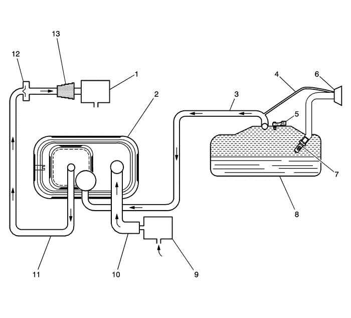
| (1) |
Evaporative Emissions (EVAP) Purge Solenoid
Valve |
| (2) |
EVAP Canister |
| (3) |
EVAP Vapor Tube |
| (4) |
Vapor Recirculation Tube |
| (5) |
Fuel Tank Pressure Sensor |
| (6) |
Fuel Filler Cap |
| (7) |
Fuel Fill Pipe Inlet Check Valve |
| (8) |
Fuel Tank |
| (9) |
EVAP Canister Vent Solenoid Valve |
| (10) |
Vent hose |
| (11) |
EVAP Purge Tube |
| (12) |
Purge Tube Check Valve, Turbo-Charged Applications
Only |
| (13) |
EVAP Canister Purge Tube Connector |
EVAP System Operation
The evaporative emission (EVAP) control system limits fuel
vapors from escaping into the atmosphere. Fuel tank vapors are
allowed to move from the fuel tank, due to pressure in the tank,
through the EVAP vapor tube, into the EVAP canister. Carbon in the
canister absorbs and stores the fuel vapors. Excess pressure is
vented through the vent hose and EVAP canister vent solenoid valve
to the atmosphere. The EVAP canister stores the fuel vapors until
the engine is able to use them. At an appropriate time, the engine
control module (ECM) will command the EVAP purge solenoid valve ON,
allowing engine vacuum to be applied to the EVAP canister. With the
normally open EVAP canister vent solenoid valve OFF, fresh air is
drawn through the vent solenoid valve and the vent hose to the EVAP
canister. Fresh air is drawn through the canister, pulling fuel
vapors from the carbon. The air/fuel vapor mixture continues
through the EVAP purge tube and EVAP purge solenoid valve into the
intake manifold to be consumed during normal combustion. The
control module uses several tests to determine if the EVAP system
is leaking or restricted.
Purge Solenoid Valve Leak Test
If the evaporative emission (EVAP) purge solenoid valve does not
seal properly fuel vapors could enter the engine at an undesired
time, causing driveability concerns. The ECM tests for this by
commanding the EVAP purge solenoid valve OFF and the canister vent
solenoid valve ON which seals the system. With the engine running,
the ECM then monitors the fuel tank pressure sensor for an increase
in vacuum. The ECM will log a fault if a vacuum develops in the
tank under these test conditions.
Large Leak Test
This diagnostic creates a vacuum condition in the EVAP system.
When the enabling criteria has been met, the control module
commands the normally open EVAP canister vent solenoid valve closed
and the EVAP purge solenoid valve open, creating a vacuum in the
EVAP system. The ECM then monitors the fuel tank pressure sensor
voltage to verify that the system is able to reach a predetermined
level of vacuum within a set amount of time. Failure to achieve the
expected level of vacuum indicates the presence of a large leak in
the EVAP system or a restriction in the purge path. The ECM will
log a fault if it detects a weaker than expected vacuum level under
these test conditions.
Canister Vent Restriction Test
If the evaporative emission (EVAP) vent system is restricted,
fuel vapors will not be properly purged from the EVAP canister. The
control module tests this by commanding the EVAP purge solenoid
valve ON while commanding the EVAP canister vent solenoid valve
OFF, and then monitoring the fuel tank pressure sensor for an
increase in vacuum. If the vacuum increases more than the expected
amount, in a set amount of time, a fault will be logged by the
ECM.
Small Leak Test
The engine off natural vacuum diagnostic is the small-leak
detection diagnostic for the evaporative emission (EVAP) system.
The engine off natural vacuum diagnostic monitors the EVAP system
pressure with the ignition OFF. Because of this, it may be normal
for the control module to remain active for up to 40 minutes after
the ignition is turned OFF. This is important to remember when
performing a parasitic draw test on vehicles equipped with engine
off natural vacuum.
When the vehicle is driven, the temperature rises in the tank
due to heat transfer from the exhaust system. After the vehicle is
parked, the temperature in the tank continues to rise for a period
of time, then starts to drop. The engine off natural vacuum
diagnostic relies on this temperature change, and the corresponding
pressure change in a sealed system, to determine if an EVAP system
leak is present.
The engine off natural vacuum diagnostic is designed to detect
leaks as small as 0.51 mm (0.020 in).
EVAP System Components
The evaporative emission (EVAP) system consists of the following
components:
EVAP Canister Purge Solenoid Valve
The EVAP canister purge solenoid valve controls the flow of vapors
from the EVAP system to the intake manifold. The purge solenoid
valve opens when commanded ON by the control module. This normally
closed valve is pulse width modulated (PWM) by the control module
to precisely control the flow of fuel vapor to the engine. The
valve will also be opened during some portions of the EVAP testing
when the engine is running, allowing engine vacuum to enter the
EVAP system.
Purge Tube Check Valve
Turbocharged vehicles have a check valve in the purge tube between
the EVAP purge solenoid valve and the EVAP canister to prevent
pressurization of the EVAP system under boost conditions. Note that
the presence of this one-way check valve prevents pressure testing
the EVAP system for leaks at the EVAP canister purge tube
connector.
EVAP Canister
The canister is filled with carbon pellets used to absorb and store
fuel vapors. Fuel vapor is stored in the canister until the control
module determines that the vapor can be consumed in the normal
combustion process.
Vapor Recirculation Tube
A vapor path between the fuel fill pipe and the vapor tube to the
carbon canister is necessary for Vehicle Onboard Diagnostics to
fully diagnose the EVAP system. It also accommodates service
diagnostic procedures by allowing the entire EVAP system to be
diagnosed from either end of the system.
Fuel Tank Pressure Sensor
The fuel tank pressure sensor measures the difference between the
pressure or vacuum in the fuel tank and outside air pressure. The
control module provides a 5 V reference and a ground to the fuel
tank pressure sensor. Depending on the vehicle, the sensor can be
located in the vapor space on top of the fuel tank, in the vapor
tube between the canister and the tank, or on the EVAP canister.
The fuel tank pressure sensor provides a signal voltage back to the
control module that can vary between 0.1-4.9 V. A high fuel tank
pressure sensor voltage indicates a low fuel tank pressure or
vacuum. A low fuel tank pressure sensor voltage indicates a high
fuel tank pressure.
Fuel Fill Pipe Check Valve
The check valve on the fuel fill pipe is there to prevent spit-back
during refueling.
EVAP Canister Vent Solenoid Valve
The EVAP vent solenoid valve controls fresh airflow into the EVAP
canister. The valve is normally open. The canister vent solenoid
valve is closed only during EVAP system tests performed by the ECM.
Fuel Fill Cap
The fuel fill cap is equipped with a seal and a vacuum relief
valve.
|
