Bosch Connectors (0.64)
Special Tools
| • |
EL-38125-580
Terminal Release Tool Kit |
| • |
J-38125-560
Terminal Release Tool |
For equivalent regional tools, refer to
Special Tools .
Terminal Removal Procedure
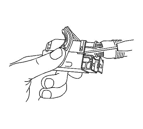
| 1. |
Locate the lever lock on the
wire dress cover. While pressing the lock, pull the lever over and
past the lock until the lever is at the end of its travel.
|
| 2. |
Disconnect the connector from
the component. |
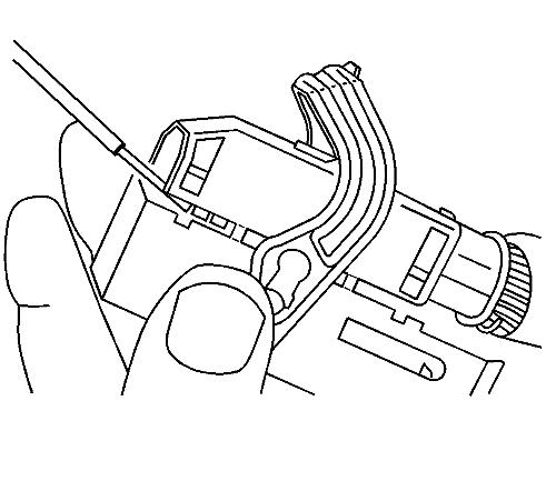
| 3. |
Pull the rubber boot that
covers the wires back to expose the end of the connector dress
cover. |
| 4. |
Place the connector locking
lever in the center of the connector. |
| 5. |
Locate the 2 dress cover
locking tabs that are on the wire end of the connector. Insert a
small flat-bladed tool between the cover and connector body and pry
up. |
| 6. |
Locate the 2 dress cover
locking tabs located on the opposite side of the connector. Insert
a small flat-bladed tool between the cover at the connector end and
pry up. |
| 7. |
Remove the dress cover.
|
| 8. |
Cut the tie wrap on the wire
bundle. |
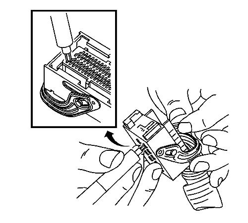
| 9. |
Remove the terminal position
assurance (TPA) by inserting a small flat-bladed tool into the
small slot in the end of the slider and pushing on the TPA until it
comes out of the connector. When the TPA exits the opposite side of
the connector, gasp the TPA and pull it completely out of the
connector. |
| 10. |
Push the wire side of the
terminal that is being removed toward the connector and hold it in
position. |
| 11. |
Insert the J-38125-560 into
the 2 triangular cavities on each side of the terminal at the front
of the connector. |
| 12. |
Carefully pull the terminal
out of the connector. Always remember never use force when pulling
a terminal out of a connector. If the terminal is difficult to
remove, repeat the entire procedure. |
| 14. |
Insert the repaired terminal
back into the cavity. Repeat the diagnostic procedure to verify the
repair and reconnect the connector bodies. |
Terminal Insertion Procedure
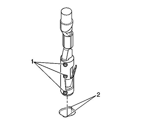
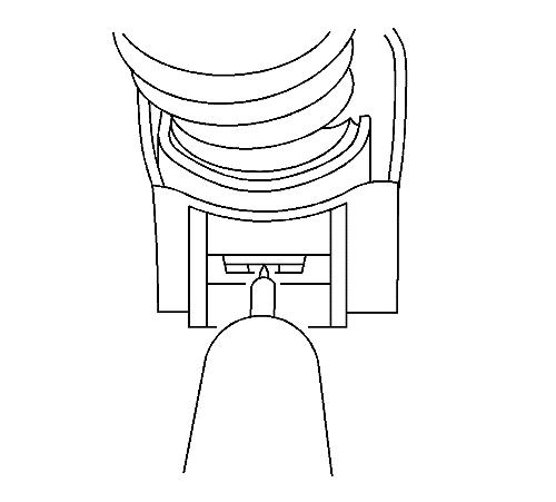
| 1. |
Prior to installation the
terminal must be aligned so the (1) coding lugs align with the (2)
coding grooves on the connector. |
| 2. |
Once the terminal is aligned,
slide the terminal into the cavity until the retainer has engaged
in the cavity of the connector. |
| 3. |
Slide the TPA in the connector
body and seat it using a small flat bladed tool. The TPA is seated
when it is flush with the contact housing. |
| 4. |
Secure the wires to the
connector body using a tie wrap and replace the dress cover and
grommet. |
|
