JST Connectors
Table 1: JST BCM Connector
Special Tools
| • |
EL-38125-580
Terminal Release Tool Kit |
| • |
J-38125-553
Terminal Release Tool |
For equivalent regional tools, refer to
Special Tools .
Terminal Removal Procedure
The JST connector family consists of seven unique connector
housings differentiated by color and keying. This connector family
is designed to use both 0.64 and 2.8 sized terminals.
JST BCM Connector
GM Service Part #
|
Color
|
88988806
|
Gray
|
88988837
|
Brown
|
88988838
|
Lt Green
|
88988839
|
Natural
|
88988840
|
Lt Blue
|
88988841
|
Black
|
88988842
|
Pink
|
|
| |
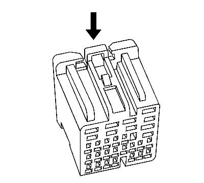
| 1. |
While depressing the lock,
remove the connector from the component. |
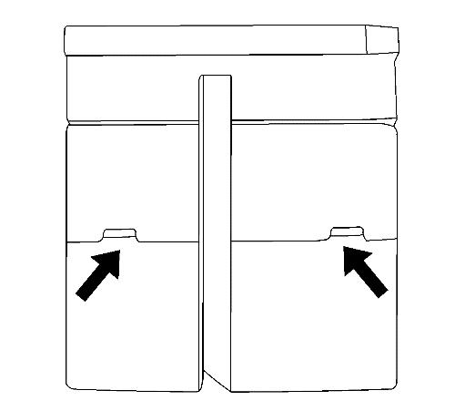
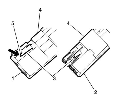
| 2. |
Unlock the terminal position
assurance (TPA): |
| |
• |
Position connector as shown
(above) and locate TPA staging cavities. |
| |
• |
Using connector terminal
release tool J-38125-553 (1) lift the TPA into the staged position.
Perform this step on both sides of the TPA. |
| |
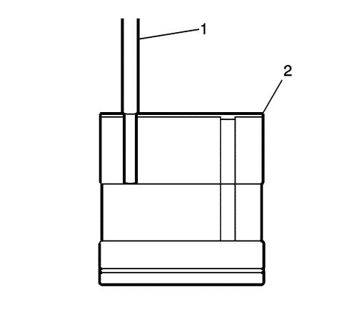
• |
You will feel the TPA click
into place when fully extended into the staged position. The figure
above shows the TPA (1) in the staged position. |
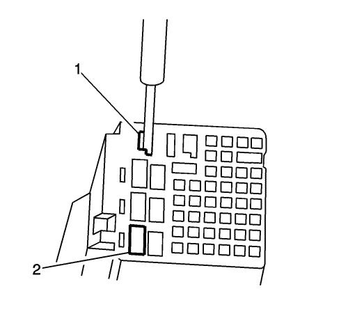
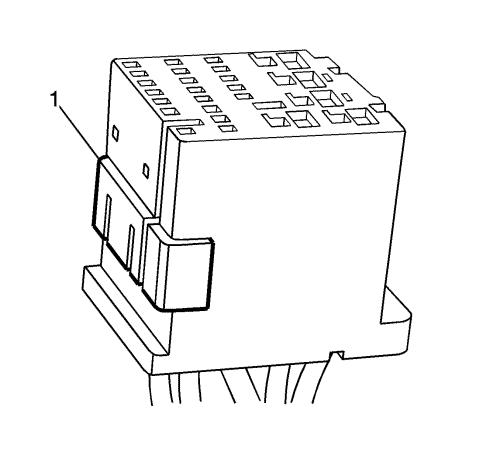
| 3. |
Release the terminal from the
connector: |
| |
• |
Position the connector as
shown (above) and locate the terminal release entry canal (1) of
the suspect terminal. |
| |
• |
Insert the connector terminal
release tool J-38125-553 into the entry canal with the angled side
of the tool facing the connector wall containing cavity 4
(2). |
| |
• |
The cavity on the left (1) is
a 2.8 mm² cavity and the cavity on the right (2) is a 0.64
mm² cavity. |
| |
• |
Place the tip of the connector
terminal release tool onto the connector lance (3) and deflect the
lance to the right (5) to release the lock. Hold this released
position. |
| |
• |
Holding the lance in the
released position, slightly pull on the suspect terminal to remove
it from the connector housing. The side TPA (4) is a secondary
lock. |
| 5. |
Insert the repaired terminal
back into the cavity. Repeat the diagnostic procedure to verify the
repair and reconnect the connector bodies. |
|
