Lower Control Arm Replacement
Special Tools
EN-45059 Angle Meter
For equivalent regional tools, refer to
Special Tools .
Removal Procedure
| 3. |
Remove wheel speed sensor
wiring harness from control arm and steering knuckle. |
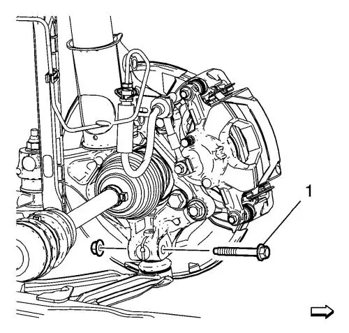
| 4. |
Remove and DISCARD the lower
ball joint to knuckle nut and bolt (1). |
| 5. |
Separate the lower control arm
from the knuckle. |
|
Caution: Do
not pry in such a way that the ball joint seal is contacted. Damage
to the seal may result. |
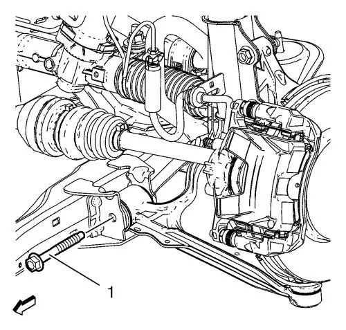
| 6. |
Remove and DISCARD the front
lower control arm nut and bolt (1). |
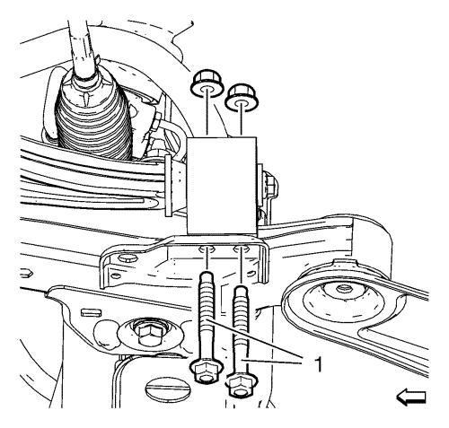
| 7. |
Remove and DISCARD the rear
lower control arm bushing nuts and bolts (1). |
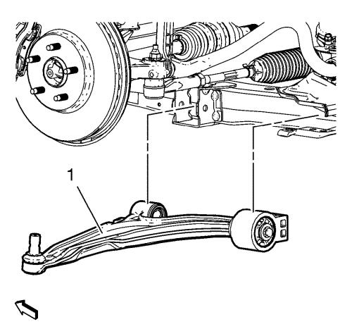
| 8. |
Remove the lower control (1)
arm from the front frame. |
Installation Procedure
| 1. |
Position the lower control arm
(1) in the cradle. |
| 2. |
Install and hand tighten the
NEW rear lower control arm bushing nuts and bolts (1). |
| 3. |
Install and hand tighten the
NEW front lower control arm nut and bolt (1). |
| 4. |
Support the lower control arm
with a hydraulic jack and lift the control arm into the neutral
position. |
| 5. |
Install the NEW ball joint to
knuckle bolt (1) with a NEW nut and tighten to 30
N·m (22 lb ft) . |
| 6. |
Tighten the ball joint to
knuckle bolt (1) and nut a final pass to an additional 60 -
75 degrees , using the EN-45059 meter
. |
| 7. |
Tighten the front and rear
lower control arm bolts and nuts a first pass to 70
N·m (52 lb ft) . |
| 8. |
Tighten the front and rear
lower control arm bolts and nuts a final pass to an additional
75 - 90 degrees , using the EN-45059
meter . |
| 9. |
Remove the jack stand.
|
|
