Electronic Component Description
Control Solenoid Valve Assembly
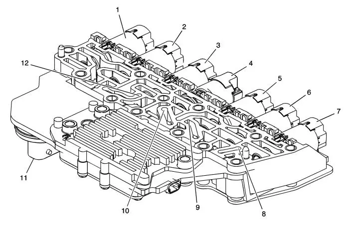
| (1) |
Pressure Control Solenoid 3 (R-1/4-5-6) |
| (2) |
(GEN 1) Pressure Control Solenoid 2 (3-5-R) |
| (2) |
(GEN 2) Pressure Control Solenoid 5 (1-2-3-4) |
| (3) |
Torque Converter Clutch (TCC) Pressure Control
Solenoid |
| (4) |
Shift Solenoid 1 (On/Off) |
| (5) |
(GEN 1) Pressure Control Solenoid 5 (1-2-3-4) |
| (5) |
(GEN 2) Pressure Control Solenoid 2 (3-5-R) |
| (6) |
Pressure Control Solenoid 4 (2-6) |
| (7) |
Line Pressure Control Solenoid |
| (8) |
(GEN 1) Transmission Fluid Pressure (TFP) Switch 1
(3-5-R) |
| (9) |
(GEN 1) Transmission Fluid Pressure (TFP) Switch 3
(2-6) |
| (10) |
(GEN 1) Transmission Fluid Pressure (TFP) Switch 4
(1-2-3-4) |
| (11) |
Pass Through Connector |
| (12) |
(GEN 1) Transmission Fluid Pressure (TFP) Switch 5
(4-5-6/R-1) |
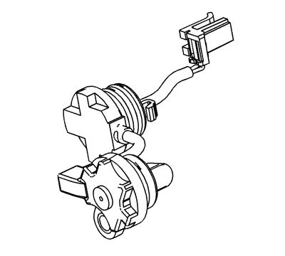
Manual Shift Detent Lever with Shaft Position Switch
Assembly
The transmission shaft position switch assembly is a sliding
contact switch attached to the manual shaft detent lever assembly
inside the transmission case. The five inputs to the TCM from the
transmission manual shift shaft switch assembly indicate the
transmission gear selector lever position. This information is used
for engine controls as well as determining the transmission shift
patterns. The state of each input is available for display on the
scan tool. The five input parameters represented are Signal A,
Signal B, Signal C, Signal P (Parity) and Signal N (P/N Start).
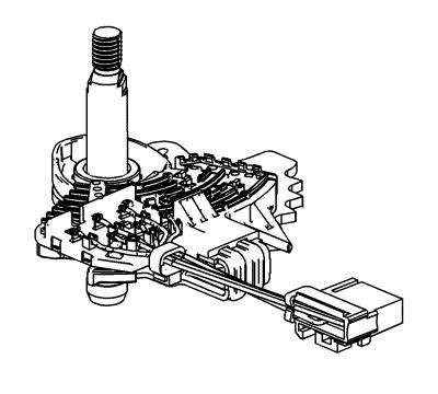
Input Speed Sensor (ISS)
The input speed sensor (ISS) is a hall-effect type sensor. The
ISS mounts to the transmission case assembly and connects to the
control solenoid (w/body and TCM) valve assembly through a wire
harness and connector. The sensor faces the 3-5-R clutch piston
housing machined teeth surface. The sensor receives 8.3-9.3 volts
on the ISS/OSS Supply Voltage circuit from the TCM. As the
3-5-R/4-5-6 clutch piston housing rotates, the sensor produces a
signal frequency based on the machined surface of the 3-5-R/4-5-6
clutch piston housing. This signal is transmitted through the ISS
signal circuit to the control solenoid (w/body and TCM) valve
assembly. The TCM uses the ISS signal to determine line pressure,
transmission shift patterns, torque converter clutch (TCC) slip
speed and gear ratio.
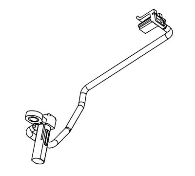
Output Speed Sensor (OSS)
The output speed sensor (OSS) is a hall-effect type sensor. The
OSS mounts to the transmission case below the control valve body
assembly and connects to the control solenoid (w/body and TCM)
valve assembly through a wire harness and connector. The sensor
faces the Park gear machined teeth surface. The sensor receives
8.3-9.3 volts on the ISS/OSS supply voltage circuit from the TCM.
As the front differential transfer drive gear assembly rotates, the
sensor produces a signal frequency based on the machined surface of
the Park gear. This signal is transmitted through the OSS signal
circuit to the TCM. The TCM uses the OSS signal to determine line
pressure, transmission shift patterns, torque converter clutch
(TCC) slip speed and gear ratio.
|