
Astra J
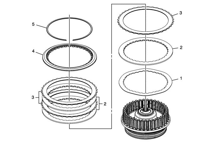
3-5-Reverse and 4-5-6 Clutch Housing Assemble (6T40/45/50 - Gen 1)Table 1: 3-5 Reverse Clutch Plates InstallationTable 2: Reluctor Wheel and Piston Installation Table 3: 4-5-6 Clutch Piston Installation Table 4: 4-5-6 Clutch Fluid Dam Installation Table 5: 4-5-6 Clutch Plates Installation Table 6: Turbine Shaft Installation 3-5 Reverse Clutch Plates Installation
|
|
|
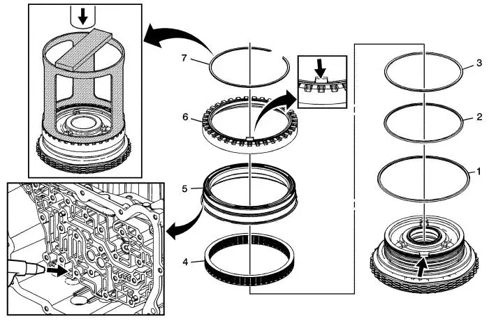
Reluctor Wheel and Piston Installation
|
|
Reluctor Wheel and Piston Installation
|
|
Callout |
Component Name |
||||
|---|---|---|---|---|---|
1 |
3-5 Reverse Clutch Piston Dam Seal (Black) |
||||
2 |
3-5 Reverse Clutch Piston Inner Seal |
||||
3 |
3-5 Reverse Clutch Piston Inner (Reluctor) Seal (Orange) |
||||
4 |
3-5 Reverse Clutch Piston Return Spring Assembly |
||||
5 |
3-5 Reverse Clutch Piston |
||||
6 |
Input Shaft Speed Sensor Reluctor Wheel |
||||
7 |
Input Shaft Speed Sensor Reluctor Ring Retainer Ring
ProcedurePlace the housing assembly onto the input shaft support inside the case. Apply shop air to the clutch fluid feed hole in the case to verify proper piston operation.Special ToolsDT-47694 Piston Spring CompressorFor equivalent regional tools, refer to Special Tools . |
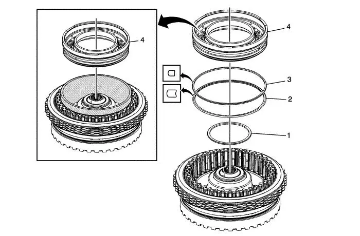
4-5-6 Clutch Piston Installation
|
|
4-5-6 Clutch Piston Installation
|
|
Callout |
Component Name |
||||||||
|---|---|---|---|---|---|---|---|---|---|
1 |
4-5-6 Clutch Piston Inner Seal |
||||||||
2 |
4-5-6 Clutch Piston Outer Seal (Large) (Rounded) |
||||||||
3 |
4-5-6 Clutch Piston Outer Seal (Dark Blue) (Stepped) |
||||||||
4 |
4-5-6 Clutch Piston Tip
Special Tools
|
| • | DT-47805 Seal Protector |
| • | DT-47951-2 Spring Compressor |
For equivalent regional tools, refer to Special Tools .
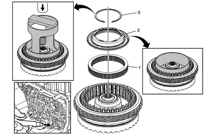
4-5-6 Clutch Fluid Dam Installation
|
|
4-5-6 Clutch Fluid Dam Installation
|
|
Callout |
Component Name |
|||||||||||
|---|---|---|---|---|---|---|---|---|---|---|---|---|
1 |
4-5-6 Clutch Piston Return Spring Assembly |
|||||||||||
2 |
4-5-6 Clutch Piston Fluid Dam Assembly Tip Special Tools
|
| • | DT-47951-1 Seal Protector for 6T40/45 applications |
| • | DT-50117 Seal Protector for 6T50 applications |
For equivalent regional tools, refer to Special Tools .
3
4-5-6 Clutch Dam Retaining Ring
| Caution: Regulate the air pressure to 276 kPa (40 psi) maximum. High pressure could cause the piston to over travel and damage the piston seals. |
Procedure
| 1. | The 4-5-6 clutch dam retaining ring is not reusable, install a NEW retaining ring. |
| 2. | Leave the seal protector in place while installing the retaining ring. |
| 3. | Place the housing assembly onto the input shaft support inside the case. Apply shop air to the clutch fluid feed hole in the case to verify proper piston operation. |
Special Tools
DT-47951-2 Spring CompressorFor equivalent regional tools, refer to Special Tools .
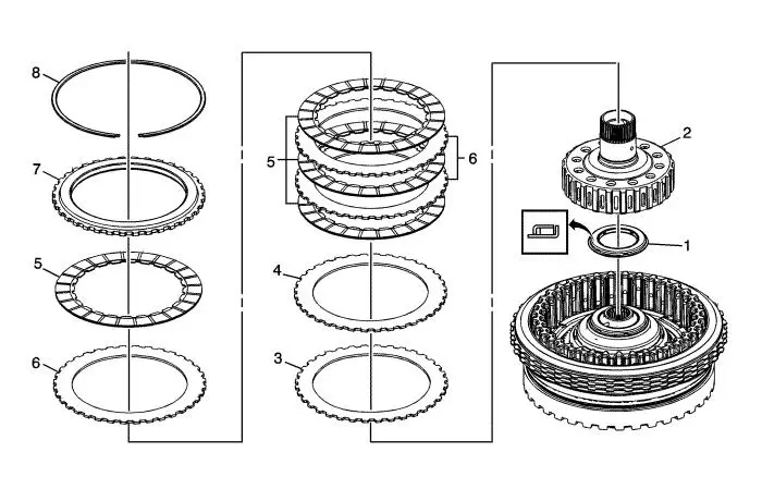
4-5-6 Clutch Plates Installation
|
|
4-5-6 Clutch Plates Installation
|
|
Callout |
Component Name |
|---|---|
1 |
Reaction Carrier Hub Thrust Bearing Assembly |
2 |
Reaction Carrier Hub Assembly |
3 |
4-5-6 Clutch Wave Plate |
4 |
4-5-6 Clutch Apply Plate |
5 |
4-5-6 Clutch Plate Assembly (Qty: 4) |
6 |
4-5-6 Clutch Plate (Qty: 3) |
7 |
4-5-6 Clutch Backing Plate |
8 |
4-5-6 Clutch Backing Plate Retaining Ring |
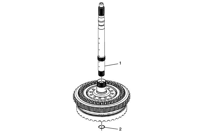
Turbine Shaft Installation
|
|
Turbine Shaft Installation
|
|
Callout |
Component Name |
|---|---|
1 |
Turbine Shaft |
2 |
Turbine Shaft Retainer Ring Tip Special ToolsGE 5586-A Circlip Pliers or equivalentFor equivalent regional tools, refer to Special Tools . |