Field Remedy: 2825
| Subject: |
Transmission M20-6/M32-6 - 5th/6th gear
scratching noises with engaged 3rd/4th gear |
| Models: |
Engines: |
Option: |
| Astra-H 2011,Astra-J 2011,Corsa-D
2011,Meriva-B 2011,Zafira-B 2011,Insignia 2011 |
All,All,All,All,All,All |
M20-6 or M32-6 transmission |
| Complaint: |
Metallic scratching noises in 3rd and 4th
gear at approx. 1800 - 2800 RPM. |
| Cause: |
Defective synchroniser ring 5th and 6th
gear. |
| Production: |
Only the transmission numbers: A2291723YZ up
to A24508217J are affected. Only the following plantes / VIN-Ranges
/ are affected: --> Plant Bochum (Astra-H) VIN W0L0AHL35B2027883
up to VIN W0L0AHL48B2084839; --> Plant Gliwice (Astra-J) VIN
W0LPD6EG5BG029353 up to VIN W0LPD6EC2BG093315; --> Plant
Ellesmere Port (Astra-J) VIN W0LPE8EFXB8018875 up to VIN
W0LPD8EG9B8066847; --> Plant Eisenach (Corsa-D) VIN
W0L0SDL08B6029571 up to VIN W0L0SDL08B6075278; --> Plant
Zaragossa (Corsa-D) VIN W0L0SDL68B4108050 up to VIN
W0L0SDL68B4247691; --> Plant Zaragossa (Meriva-B) VIN
W0LSH9EE5B4067858 up to VIN W0LSH9EE3B4222469; --> Plant Bochum
(Zafira-B) VIN W0L0AHM75B2028834 up to VIN W0L0AHM75B2081845;
--> Plant Ruesselsheim (Insignia) VIN W0LGM6EC2B1048605 up to
VIN W0LGM5GB5B1126535. |
Remedy:
In case of customer complaint replace the synchronizer rings
of the 5th and the 6th gear.
Note:
Affected transmission range = A2291723YZ - A24508217J.
Transmission coding see working procedure
“Transmission Identification”, group “K”, Service Instruction Corsa-D
– Document Number 01501473.
Working Procedure:
1. Remove transmission
    - see Working Procedure "Transmission, Remove and Install” or
      “Transmission Replacement”, Group "K" or Group “Transmission”
      in the corresponding Service Instruction
2. Install KM-6115 to transmission
- Fix it with 2 bolts
3. Install transmission with KM-6115 to work bench
- Install and secure KM-6115 to KM-113-2
    Note:
    2nd technician required.
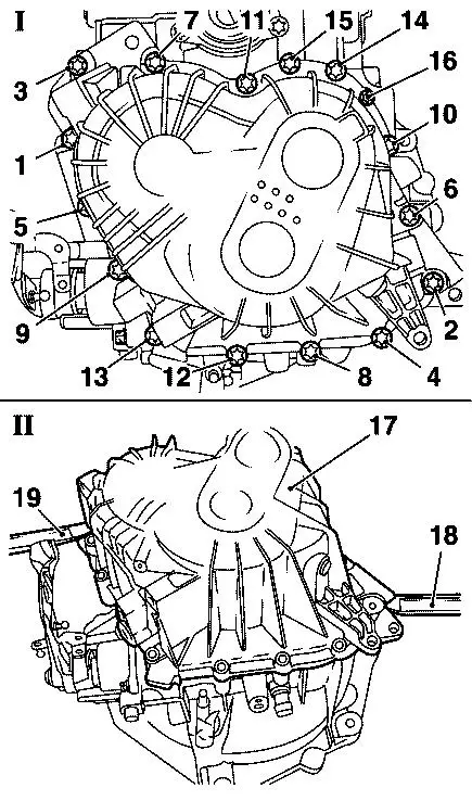
4. Loosen transmission cover (Picture I)
- Remove 16 bolts (1-16)
5. Remove transmission cover (Picture II, 17)
    - Lift up transmission cover constant with suitable tools (18)
      and (19)
    Note:
    Not thumping or striking.
6. Remove reverse lamp switch
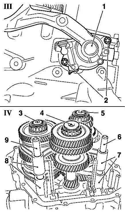
7. Remove shifter (Picture III, 1)
    - Shift transmission into NEUTRAL
    - Remove 2 bolts (2)
 8. Remove 3 transmission shafts with shift forks completely
    (Picture IV)
    - Remove transmission shafts (3, 4 and 5) together with
      shift shafts (6 and 9) and shift forks (7 and 8)
    - Remove shift forks and shift shafts from transmission shafts
      and lay aside
    Important:
    Put parts on a clean surface.
    Note:
    For better orientation make a sketch of the single parts.
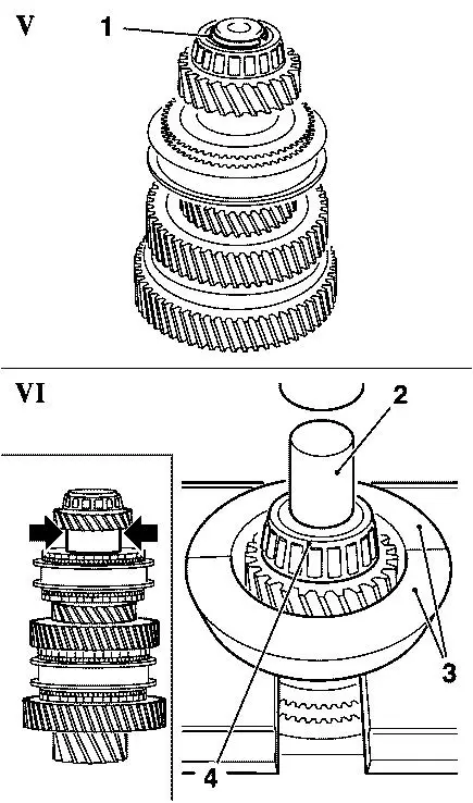
 9. Remove snap ring from lower main shaft (Picture V, 1)
10. Remove bearing from lower main shaft (Picture VI, 4)
- Support lower main shaft with suitable tool (3)
    Note:
    Support lower main shaft below 6th drive gear (arrows)
- Press-out bearing with suitable pressure pad (2)
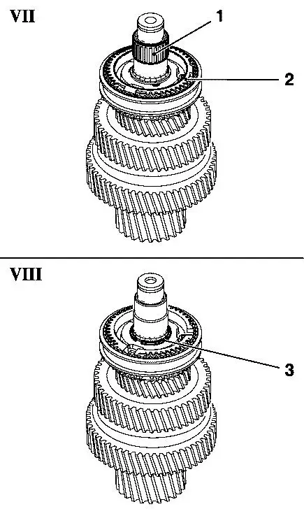
11. Remove needle bearing 6th drive gear from lower main shaft
    (Picture VII, 1)
12. Remove 6th gear synchroniser ring (Picture VII, 2)
13. Remove snap ring synchroniser body 5th/6th gear from lower
    main shaft (Picture VIII, 3)
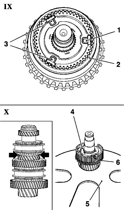
14. Disassemble synchroniser body 5th/6th gear (Picture IX)
    - Remove shift collar (2)
    - Remove 3 sliding blocks (1 and 3)
15. Remove synchroniser body 5th/6th gear from lower main shaft
    (Picture X, 4)
- Support lower main shaft using KM-307-B (5)
    Note:
    Support lower main shaft below 5th drive gear (arrows).
    - Press-out synchroniser body 5th/6th gear using a suitable
      pressure pad
    - Remove 5th drive gear and 5th drive gear synchroniser ring
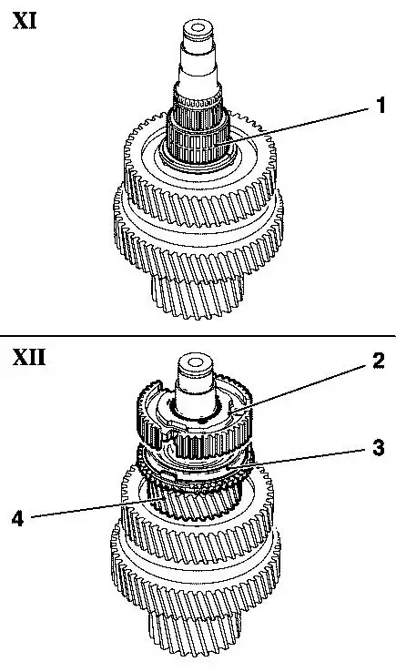
16. Install 5th drive gear needle bearing to lower main shaft
    (Picture XI, 1)
17. Install 5th drive gear to lower main shaft (Picture XII, 4)
18. Install NEW 5th drive gear synchroniser ring (Picture XII, 3)
19. Attach synchroniser body 5th/6th gear to lower main shaft
    (Picture XII, 2)
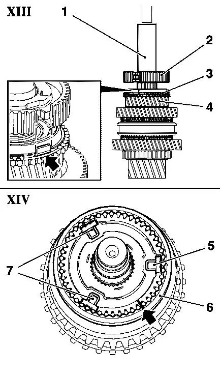
20. Install synchroniser body 5th/6th gear to lower main shaft
    (Picture XIII, 2)
    Important:
    Align 5th drive gear synchroniser ring to synchroniser
    body 5th/6th gear (arrow)
    - Press-on synchroniser body 5th/6th gear using pressure pad (1)
      of repair kit
    - Pressure force approx. 800 kg
21. Assemble synchroniser body 5th/6th gear (Picture XIV)
    - Attach 3 sliding blocks (5 and 7)
    - Attach shift collar (6)
    Important:
    Synchroniser body and shift collar must be installed later
    in the same setting. Pay attention to markings (arrow).
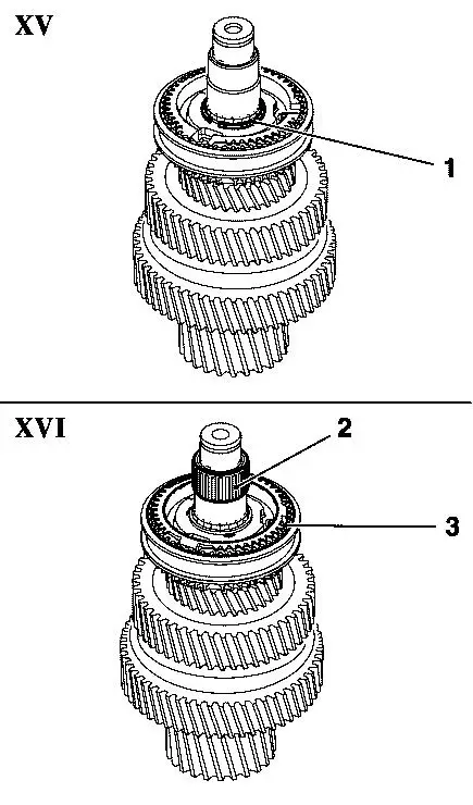
22. Install synchroniser body 5th/6th gear snap ring to lower
    main shaft (Picture XV, 1)
23. Install 6th drive gear needle bearing to lower main shaft
    (Picture XVI, 2)
24. Install NEW 6th drive gear synchroniser ring (Picture XVI, 3)
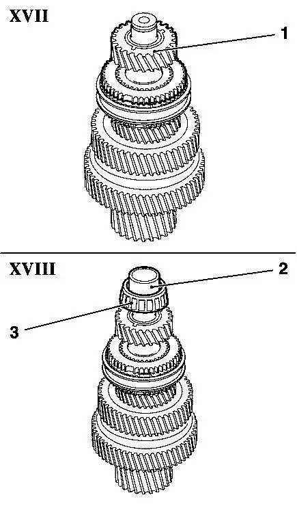
25. Install 6th drive gear to lower main shaft (Picture XVII, 1)
26. Install bearing to lower main shaft (Picture XVIII, 3)
    - Press-on bearing using pressure pad (2) of repair kit
    - Pressure force approx. 800 kg
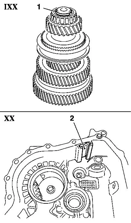
27. Install NEW snap ring to lower main shaft (Picture IXX, 1)
    Important:
    Measure thickness of old snap ring using a digital slide
    gauge or a micrometer.
- Install new snap ring in the same thickness
28. Clean magnet (Picture XX, 2)
29. Install 2 main shafts into transmission housing
    - Attach main shafts
    - Install 2 lower shift forks to shift collars
30. Install input shaft
    - Lightly lift up lower main shaft
    - Install input shaft
    Note:
    Pay attention to the gear teeth of the transmission shafts.
31. Install 2 upper shift forks to shift collars
32. Install 2 shift shafts
    Important:
    Pay attention for correct seat!
33. Install shifter
- Tighten 2 bolts - 20 Nm
34. Install reverse lamp switch
- Tighten switch - 20 Nm
35. Apply sealing compound to transmission cover
    - Apply sealing compound Loctite 518 uninterrupted with
      2-3 mm thickness
36. Install transmission cover
    Important:
    Bolt “6” (refer to picture I) has to be installed in its
    original position!
    Pay attention to tightening sequence of the bolts shown in
    picture “I”:
    Bolts 1 to 15 – outer torx
    Bolt 16 – inner torx
    - tighten 16 bolts
    - 1st step: 5 Nm
    - 2nd step: 21 Nm
    Important:
    Check for correctness!
    Re-tighten all bolts clockwise with 21 Nm
37. Perform shift function test
    - Shift every gear
    - Turn input shaft
    Note:
    If necessary attach clutch disc.
38. Install transmission
    - see Working Procedure “Transmission, Remove and Install” or
      “Transmission Replacement”, Group “K” or Group “Transmission”
      in the corresponding Service Instruction
Spare-Parts: Part-No.: Catalogue-No.:
Repair Kit 55583569 16 07 021
Labour Times:
U3 282 50 5th/6th Gear Synchronizer Rings Replacement
Astra-H TC: Hours:
Z13DTH                                  90             6.5
A16LET, Z16LET                          90             6.2
Z20 LEL, Z20LER, Z20LEH                 90             5.9
A17DTJ, A17DTR, Z17DTH, Z17DTJ, Z17DTR  90             6.3
Z19DTH, Z19DTL, Z19DT                   90             7.4
Corsa-D TC: Hours:
Z13DTH, Z13DTR                          90             5.5
Z16LEL, A16LEL, Z16LER, A16LER          90             5.3
Z17DTR, A17DTS                          90             5.7
Zafira-B TC: Hours:
A16XNT, Z16XNT                          90             6.5
Y20LER, Z20LEH, Z22YH                   90             5.7
A17DTJ, A17DTR, Z17DTJ                  90             6.2
Z19DTL, Z19DT, Z19DTH                   90             6.7
Astra-J TC: Hours:
A14NEL, A14NET, A16LET                  90             5.9
A17DTJ, A17DTR                          90             6.1
Insignia TC: Hours:
A16XER, A18XER                          90             4.9
A16LET                                  90             5.0
A20NHT / A20NFT: AWD                    90             5.6
A20NHT: AWD                             90             6.6
A28NET, A28NER                          90             7.4
A20DTC, A20DTJ, A20DTH, A20DTL, A20DT   90             6.8
A20DTR                                  90             7.9
Meriva-B TC: Hours:
A13DTC                                  90             7.5
A14XER, A14NEL                          90             6.7
A14NET                                  90             7.3
The costs for this repair will be covered during warranty and policy.
For policy please refer to the Policy Guideline (WebPG/Kuugel).
The regular Warranty Procedure will apply.
| FunctionalGroup: |
K - Clutch/Transmission |
| Complaint Group: |
14 - Noises or Vibrations |
| Trouble Code: |
None |
|
