Engine, Repair Using Short-block
 Remove, Disconnect Remove, Disconnect Remove engine with transmission - see corresponding operation. Remove attaching aggregates and transmission - see corresponding operation. Attach engine to Engine Overhaul Stand KM-412 with Adapters KM-412-3. Place collecting basin underneath and drain engine oil. Release engine vent hose from cylinder head cover (1) and remove. Detach vacuum hose from fuel pressure regulator and connection hoses from tank vent valve. Detach engine vent hose from upper part of intake manifold. Release air intake pipe (2) - for this purpose release throttle body hose clamp and detach air intake pipe together with wiring trough bracket from lower part of intake manifold as well as from wiring harness plug bracket (illus. II shows C 16 XE). For C 16 XE: detach throttle body from upper part of intake manifold (3). | 
|
Remove, Disconnect Detach upper part of intake manifold from lower part of intake manifold and from cylinder head (1). For X 14 XE, C 14 SEL, X 16 XE, C 16 SEL: release connection hose upper hose clamp from throttle body (2).
 Clean Clean Remove old gasket and gasket residue, clean all sealing surfaces.
Remove, Disconnect For all engines: remove increment disc from crankshaft - for this purpose lock flywheel via starter ring gear using KM-652 (see illus. III). | 
|
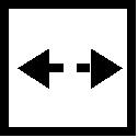
Remove, Disconnect Remove upper (1) and lower parts of toothed belt cover (2) (arrows, see illus. I). Release toothed belt tension roller and remove tension-free toothed belt. Disconnect spark plug connectors. Remove cylinder head cover from cylinder head (10 bolts). Remove camshaft pulleys from camshafts - for this purpose counterhold camshaft at lug provided at 1st cylinder (see illus. II). | 
|
Remove, Disconnect Remove toothed belt tension roller and both guide rollers. Unscrew fastening bolts (arrows) and remove rear toothed belt cover from front face of engine. Remove inductive crankshaft pulse pickup and camshaft pulse pickup as well as coolant pump and starter. Remove crankcase ventilation flange and line. | 
|
Remove thrust plate with clutch disc.
 Important! Important! When reusing clutch assembly mark thrust plate against flywheel (see illus.).
Remove, Disconnect Lock flywheel via starter ring gear with KM-652 and remove. | 
|
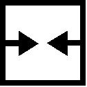
Remove, Disconnect Release cylinder head bolts in a spiral pattern (see illus.) from inside outwards initially with 1/4 turn and then 1/2 turn. Remove cylinder head bolts and lift cylinder head from cylinder block. Remove centring sleeves from cylinder block. | 
|
Remove, Disconnect Remove oil pan from cylinder block. Illustration shows a sheet metal oil pan. Remove oil intake pipe and oil pump. Detach knock sensor from cylinder block.
Clean Clean all removed parts and sealing surfaces. | 
|
 Inspect Inspect Check all parts for damage and wear and replace if necessary. Check cylinder head for plane surface - see corresponding operation.
 Install, Connect Install, Connect Assemble new short block. Emboss engine number into cylinder block (arrow) with numbers punch. Drive centring sleeves with KM-427 to stop in cylinder block. | 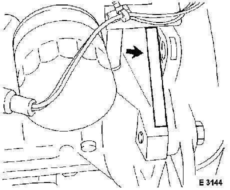
|
Install flywheel with new bolts and lock via starter ring gear using KM-652. Flywheel to crankshaft - 35 Nm / 26 lbf. ft. + 30 ° + 15 ° 1) 2) . Install clutch assembly - see operation "Clutch Disc, Remove and Install" in group "K". | 
|
1) Re-cut thread in crankshaft. 2) Use new fastening bolts.
Install, Connect Install oil pump. Slide protective sleeve for KM-417 onto crankshaft journal. Install oil pump with new gasket and new seal ring (7 bolts, arrows). Lightly coat seal lip of seal ring with silicone grease (white) before installation.
 Tighten (Torque) Tighten (Torque) Oil pump to cylinder block - 10 Nm / 7 lbf. ft. | 
|
Install, Connect Install oil intake pipe with new seal ring. Oil intake pipe to oil pump - 8 Nm / 6 lbf. ft. 1)
. Oil intake pipe (bracket) to cylinder block - 8 Nm / 6 lbf. ft. | 
|
1) Bolts must be re-cut before re-use and inserted after being coated with bolt locking compound (red).
Install, Connect Coat joints of sealing surfaces on cylinder block (arrows) with adhesive sealing compound (black). | 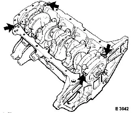
|
Install oil pan with new gasket. Screw in oil drain plug with new seal ring.
Important! Version with aluminium oil pan: before tightening fastening bolts, oil pan must be aligned to cylinder block using alignment straight edge, in order to ensure correct gap-free seating at transmission housing. | 
|
Tighten (Torque) Oil pan to cylinder block and oil pump - 10 Nm / 7 lbf. ft. 1)
.
|
Oil pan to transmission housing |
Aluminium oil pan |
M8 - 20 Nm / 15 lbf. ft., M10 - 40 Nm / 29.5 lbf. ft. |
|
Oil drain plug (inner torx bolt) to |
aluminium oil pan |
- 14 Nm / 10 lbf. ft. |
|
Oil drain plug (hex bolt) to |
Aluminium oil pan |
- 45 Nm / 33 lbf. ft. |
|
Oil drain plug to oil pan |
Sheet metal oil pan |
- 55 Nm / 41 lbf. ft. |
Install, Connect | 
|
Install new cylinder head gasket with identification OBEN/TOP on top and pointing towards engine timing side. Position cylinder head on cylinder block - 1st cylinder in 60 ° before "TDC" position. | 
|
1) Bolts must be re-cut before re-use and inserted after being coated with bolt locking compound (red). Installation time including the torque check is max. 10 min.
Install, Connect Insert new cylinder head bolts and tighten in a spiral pattern from inside outwards in four stages.
 Torque - Angle Method Torque - Angle Method Cylinder head to cylinder block - 25 Nm / 18 lbf. ft. + 90 ° + 90 ° + 90 ° + 45 ° 1)
. | 
|
Install, Connect Install rear toothed belt cover (arrows). Install both camshaft pulleys - for this purpose counterhold camshaft at lug provided at 1st cylinder |
|
1) In case of angle specifications, tighten bolts with corresponding torques. Then turn further by the specified angle Use new bolts.
Install, Connect Replace seal ring for coolant pump and lightly coat sealing surface with silicone grease (white). Insert coolant pump and bolt on - 8 Nm / 6 lbf. ft.
Important! The mark on coolant pump must align with the mark on the cylinder block (see illus.). | 
|
Install, Connect Install toothed belt tension roller - 20 Nm / 15 lbf. ft.
Important! Ensure installation position is correct. Insert lug (1) of tension roller base plate into recess (2) of oil pump housing. | 
|
Install, Connect Install both toothed belt guide rollers (arrows). The large guide roller is positioned on intake side.
Tighten (Torque)
|
Toothed belt guide roller on exhaust side to cylinder block |
- 25 Nm / 18 lbf. ft. |
|
Toothed belt guide roller on intake side to cylinder block |
- 25 Nm / 18 lbf. ft. |
Install, Connect | 
|
Adjust valve timings and install toothed belt - see corresponding operation. Attach camshaft sensor to cylinder head - 8 Nm / 6 lbf. ft. 1) . Fit crankshaft pulse pick-up bracket to oil pump (see illus.) - 10 Nm / 7 lbf. ft. Camshaft pulleys with new fastening bolts to camshaft - tightening torque 50 Nm / 37 lbf. ft. + 60 ° + 15 ° . | 
|
1) Insert bolts coated with bolt locking compound (red).
Install, Connect Insert new moulded part gasket (1) and new O-rings (2) into cylinder head cover.
Important! Insert O-rings with a little silicone grease (white) into cylinder head cover, so that they do not fall into cylinder head when being installed. Before installing the cylinder head cover, the areas at the outer edges of the front camshaft bearing cap must be coated with adhesive sealing compound (black).
Install, Connect | 
|
Fit cylinder head cover with new seals to cylinder head. Tighten bolts in a spiral pattern from the inside outwards (see illus.) - 8 Nm / 6 lbf. ft. Attach spark plug connectors. Attach upper and lower toothed belt cover to rear toothed belt cover - 4 Nm / 3 lbf. ft. | 
|
Install, Connect For C 16 XE: attach upper part of intake manifold to lower part of intake manifold and to cylinder head (arrow). Ensure correct seating of moulded part gasket - 8 Nm / 6 lbf. ft. Throttle body with new gasket to upper part of intake manifold - 8 Nm / 6 lbf. ft. | 
|
For X 14 XE, C 14 SEL, X 16 XE, C 16 SEL: attach upper part of intake manifold with new gasket to lower part of intake manifold and to cylinder head cover (7 bolts) - 8 Nm / 6 lbf. ft. Fit connection hose for throttle body to upper part of intake manifold (3). Attach hoses (1) and (2). | 
|
Install, Connect For all engines: Install air intake pipe. For this purpose, fasten hose clamp to throttle body and attach air intake pipe together with wiring trough bracket to lower part of intake manifold (8 Nm / 6 lbf. ft.) and to wiring harness plug bracket (5 Nm / 4 lbf. ft.) (arrows). Illustration shows C 16 XE. | 
|
Mount flywheel on crankshaft and align. Lock flywheel via starter ring gear with KM-652 (starter side) and attach with new bolts - 35 Nm / 26 lbf. ft. + 30 ° + 15 ° 1)
. Fasten increment disc (with toothed belt drive gear) with new bolt to crankshaft - 95 Nm / 70 lbf. ft. + 30 ° + 15 ° 1) |
|
1) In case of angle specifications, tighten bolts with corresponding torques. Then turn further by the specified angle Use new bolts.
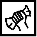
Install, Connect Install clutch assembly (see illus.) - see corresponding operation in group "K". Coat seal ring of oil filter cartridge with engine oil and hand-tighten oil filter cartridge. Fill engine oil up to "MAX" on dipstick. | 
|
Bolt knock sensor with KM-728-A (1) to cylinder block.
Important! The recommended torque value must be observed; otherwise malfunctions may occur. The recommended torque value is attained before the knock sensor contacts the cylinder block fully.
Tighten (Torque) Knock sensor to cylinder block (M 8) - 20 Nm / 15 lbf. ft. Knock sensor to cylinder block (M 10) 12.5 Nm / 9.2 lbf. ft. | 
|
Install, Connect Attach engine vent pipe (see illus.) with new gasket to cylinder block - 8 Nm / 6 lbf. ft. Attach hose to cylinder head cover. Re-attach or re-connect all hoses or wiring harness plugs which have been detached. Attach attaching parts and bolt transmission (manual or automatic) to cylinder block (60 Nm / 44 lbf. ft.) - see corresponding operations. Install coolant pipe and secure to transmission. | 
|
Remove, Disconnect Dismantle engine from Engine Overhaul Stand KM-412 and Adapter KM-412-3 from engine.
Install, Connect Install engine with transmission - see operation "Engine with Transmission, Remove and Install". | 
|
|
