Cylinder Head, Remove and Install
 Important! Important!
• Only remove cylinder head on cold engine.
• Wiring harnesses and wiring troughs which have to be released or removed during this operation must be re-fastened in their respective original positions using genuine parts from "Aftersales" (cable ties, clips etc.).
• It must be ensured, that after installation of the cylinder head, wiring harnesses, vacuum hoses and coolant hoses are routed in such a way that they cannot chafe on hot or rotating parts and thus become damaged.
• The utmost care must be taken when cylinder head is removed from or positioned on cylinder block - ensure that no attaching parts are damaged.
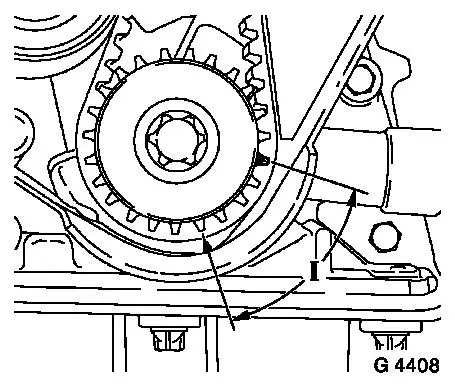
• Before removing toothed belt - set crankshaft to approx. 60 ° (dimension I) before TDC mark.
| 
|
 Remove, Disconnect Remove, Disconnect Remove air cleaner housing - see illustration "Air Ducts (X 14 XE, C 14 SEL, X 16 XE, C 16 SEL)" or "Air Ducts (C 16 XE)". Remove upper part of intake manifold - see operation "Intake Manifold - Upper Part, Remove and Install (C 16 XE)" or "Intake Manifold - Upper Part, Remove and Install (X 14 XE, C 14 SEL, X 16 XE, C 16 SEL)". For version with secondary air system: Remove air duct hose (1) and vacuum hose (2) from secondary air combination valve. Disconnect wiring harness plug for secondary air pump (3). Remove fastening nuts (4) and remove secondary air pump assembly (5). | 
|
Remove, Disconnect Detach spark plug connector with MKM-836 from spark plugs and unclip from brackets - note routing of spark plug wire. Detach wiring harness plug from DIS ignition module (1) and detach DIS ignition module from bracket. Remove lower coolant hose (2) from radiator - collect escaping coolant. Remove upper coolant hose (3) from thermostat housing. | 
|
Remove, Disconnect Detach wiring harness plug (1) from intake manifold pressure sensor (2) and remove intake manifold pressure sensor from bulkhead. Remove coolant compensation tank (3) - for this, remove compensation tank from bulkhead and detach coolant hoses (3 off) from compensation tank. Detach accelerator Bowden cable (4) from curved disc and lay aside. Reduce fuel pressure with Fuel Pressure Gauge KM-J-34730-91 via test connection - collect escaping fuel in suitable container - note safety regulations and national legislation. Detach fuel lines (5) from fuel distributor pipe and from fuel pressure regulator and lay aside. | 
|
Remove, Disconnect Detach or disconnect all wiring connections which are connected to the wiring trough or wiring harness (1) and place out of way - note cable routing. Unclip wiring trough from wiring trough bracket and release from throttle body - set aside wiring trough with wiring harness. Detach wiring trough bracket (2) and air intake pipe (3) from lower part of intake manifold. Detach air intake pipe from throttle body - push air intake pipe slightly downwards. | 
|
Remove, Disconnect Remove connection port (1) from throttle body flange. Remove fastening bolts (2) and lay throttle body aside. Disconnect wiring harness plug from idle speed stepper motor (3) and throttle valve potentiometer (4). Detach coolant hoses (5) from throttle body - remove throttle body. | 
|
Remove, Disconnect Separate or detach wiring harness plug for exhaust gas recirculation valve, knock sensor, camshaft sensor and wiring harness plug for injectors. Release injector wiring harness (1) and remove upwards - note routing of wiring harness. Release wiring harness plug for camshaft sensor and wiring harness plug for crankshaft pulse pick-up. For version without AC: remove ribbed V-belt - see operation "Ribbed V-belt, Remove and Install (Vehicles without Power Steering and AC)" or "Ribbed V-belt, Remove and Install (Vehicles with Power Steering)". For version with AC: detach ribbed V-belt from alternator pulley and set aside (do not remove) - see operation "Ribbed V-belt, Remove and Install (Vehicles with Power Steering and AC)". Remove upper alternator fastening bolt (arrow) and release lower fastening bolt - swing alternator to rear. | 
|
Remove, Disconnect Detach coolant hose from coolant port (1). Detach fastening clamp for power steering pump pressure line (2) from secondary air combination valve bracket. | 
|
Remove, Disconnect Remove upper part of toothed belt cover (1) - see operation "Toothed Belt Cover - Upper Part, Remove and Install". Remove toothed belt cover - lower part (2) - see operation "Toothed Belt Cover - Lower Part, Remove and Install". Remove front exhaust pipe (3) from exhaust manifold. For version with air conditioning: Remove exhaust manifold (4) - see operation "Exhaust Manifold, Remove and Install (C 16 XE)" or "Exhaust Manifold, Remove and Install (X 14 XE, C 14 SEL, X 16 XE, C 16 SEL)". | 
|
Important! Before removing toothed belt - set crankshaft to approx. 60 ° before TDC mark.
Remove, Disconnect Remove toothed belt (3) - see operation "Toothed Belt, Remove and Install". Remove toothed belt tension roller (4) - see operation "Toothed Belt Tension Roller, Remove and Install". Remove toothed belt guide roller (5) - see operation "Toothed Belt Guide Roller, Remove and Install". Remove cylinder head cover (1) - see operation "Cylinder Head Cover, Remove and Install". Remove camshaft pulleys (6) - see operation "Camshaft Pulleys, Remove and Install". Remove rear toothed belt cover (2) - see operation "Toothed Belt Cover - Rear, Remove and Install". | 
|
Remove, Disconnect Release cylinder head bolts in sequence illustrated - first 1/4 turn, then 1/2 turn, and remove.
Important! Raise cylinder head and remove coolant hose from lower part of intake manifold (arrow) - remove cylinder head. | 
|
 Clean Clean Remove gasket remnants and clean sealing surfaces.
 Inspect Inspect Check length and width of cylinder head sealing surfaces for deformation and diagonals for warpage - use straight edge.
Important! Resurfacing of the cylinder head is not permitted.
 Measure Measure Height of cylinder head (sealing surface to sealing surface). Dimension (I) - 135 mm ± 0.10 mm. | 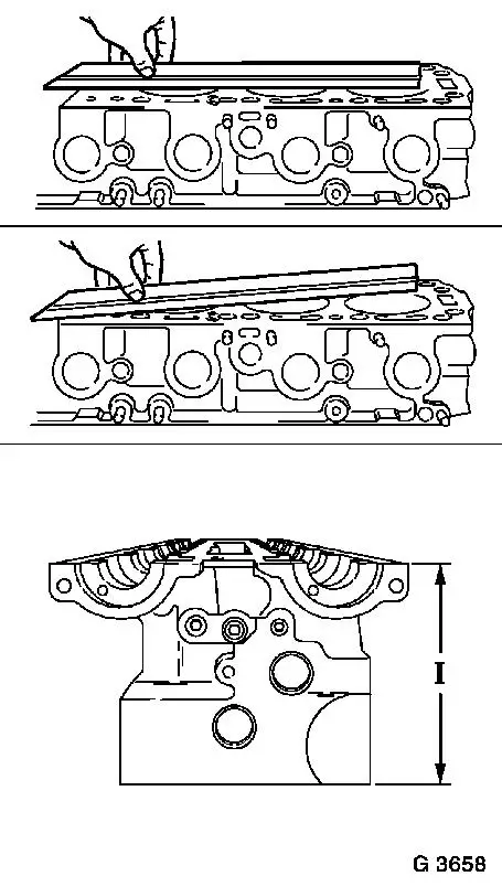
|
 Install, Connect Install, Connect Place new cylinder head gasket on cylinder block with identification "OBEN/TOP" uppermost.
Important! Lift cylinder head into engine compartment and attach coolant hose to lower part of intake manifold - place cylinder head on cylinder block after attaching coolant hose.
Install, Connect Position cylinder head on cylinder block and fasten with new cylinder head bolts in illustrated sequence with KM-610 and KM-470-B - tightening torque 25 Nm / 18 lbf. ft. + 90 ° + 90 ° + 90 ° + 45 ° | 
|
Install, Connect Install rear toothed belt cover - see operation "Rear Toothed Belt Cover, Remove and Install". Install camshaft sprockets - see operation "Camshaft Sprockets, Remove and Install". Install cylinder head cover - see operation "Cylinder Head Cover, Remove and Install." Install upper part of intake manifold - see operation "Intake Manifold - Upper Part, Remove and Install (C 16 XE)" or "Intake Manifold - Upper Part, Remove and Install (X 14 XE, C 14 SEL, X 16 XE, C 16 SEL)". Install toothed belt guide roller - see operation "Toothed Belt Guide Roller, Remove and Install". Install toothed belt tension roller - see operation "Toothed Belt Tension Roller, Remove and Install".
 Adjust Adjust Position camshafts first and then crankshaft to "1st cylinder ignition TDC" marks (short path) and secure camshaft pulleys with KM-852 - see operation "Timing, Adjust".
Install, Connect Install toothed belt - see operation "Toothed Belt, Remove and Install".
Install, Connect For version with AC: install exhaust manifold (4) - see operation "Exhaust Manifold, Remove and Install (C 16 XE)" or "Exhaust Manifold, Remove and Install (X 14 XE, C 14 SEL, X 16 XE, C 16 SEL)". Attach front exhaust pipe to exhaust manifold - tightening torque 20 Nm / 15 lbf. ft. Install toothed belt cover - lower part - see operation "Toothed Belt Cover - Lower Part, Remove and Install". Install upper part of toothed belt cover - see operation "Toothed Belt Cover - Upper Part, Remove and Install". Attach power steering pump pressure line to secondary air combination valve bracket. Attach coolant hose to coolant connection. Attach alternator to alternator shackle - tightening torque 20 Nm / 15 lbf. ft. Tighten lower alternator fastening bolt - tightening torque 35 Nm / 26 lbf. ft. Install ribbed V-belt - see operation "Ribbed V-belt, Remove and Install (Vehicles without Power Steering and AC)" or "Ribbed V-belt, Remove and Install (Vehicles with Power Steering)" or "Ribbed V-belt, Remove and Install (Vehicles with Power Steering and AC)". Route wiring harness plug for camshaft sensor and wiring harness plug for crankshaft pulse pick-up and clip into corresponding bracket.
Install, Connect Route and connect injector wiring harness. Attach coolant hoses to throttle body. Attach wiring harness plug to idle speed stepper motor and to throttle valve potentiometer. Attach throttle valve connection with new gasket to throttle body flange - tightening torque 8 Nm / 6 lbf. ft. Attach connection port to throttle body flange. Attach wiring trough bracket and air intake pipe to lower part of intake manifold - tightening torque 8 Nm / 6 lbf. ft. Attach air intake pipe to throttle body - ensure correct seating. Clip wiring trough for engine cable bundle to wiring trough bracket and secure to throttle body - connect / attach required cable connections. Attach fuel feed line to fuel distributor pipe and fuel return line to fuel pressure regulator - tightening torque 15 Nm / 11 lbf. ft. Attach accelerator Bowden cable to curved disc and bracket.
Install, Connect Attach coolant hoses to coolant compensation tank and coolant compensation tank to bulkhead. Attach intake manifold pressure sensor to bulkhead and wiring harness plug to intake manifold pressure sensor. Attach upper coolant hose to thermostat housing and lower coolant hose to radiator. Attach DIS ignition module to DIS ignition module bracket - tightening torque 8 Nm / 6 lbf. ft. Connect spark plug connectors to spark plugs and clip ignition cables into brackets - note ignition cable routing.
Install, Connect For version with secondary air system: attach secondary air pump assembly to bracket - tightening torque 20 Nm / 15 lbf. ft. Connect secondary air pump wiring harness plug. Connect air duct hose and vacuum hose to secondary air combination valve. Install upper part of intake manifold - see operation "Intake Manifold - Upper Part, Remove and Install (C 16 XE)" or "Intake Manifold - Upper Part, Remove and Install (X 14 XE, C 14 SEL, X 16 XE, C 16 SEL)". Install air cleaner housing - see illustration "Air Ducts (X 14 XE, C 14 SEL, X 16 XE, C 16 SEL)" or "Air Ducts (C 16 XE)".
Inspect Top up cooling system - see operations "Cooling System, Top Up and Bleed" and "Cooling System, Check for Leaks".
|
