Injectors, Remove and Install (X 14 XE, C 14 SEL, X 16 XE, C 16 SEL)
 Important! Important! Fuel system is pressurised: Reduce fuel pressure with Pressure Tester KM-J-34730-91 via testing port - collect escaping fuel in suitable container - observe safety regulations and national legislation.
 Remove, Disconnect Remove, Disconnect Remove closure cap from oil filler aperture, unscrew fastening bolts (1) and remove ignition cable cover (see illus. I). Remove engine vent hose (2) and brake servo vacuum hose (3) from upper part of intake manifold. Remove tank vent valve upwards from bracket and lay aside. Disconnect vacuum hose for intake manifold pressure sensor (5) and connection hose of tank vent valve (4) from upper part of intake manifold. Detach upper hose clamp of connection hose from throttle body (6). | 
|
Remove, Disconnect Unbolt upper part of intake manifold from lower part of intake manifold and from cylinder head cover (arrows) and remove.
 Clean Clean Remove old gasket and gasket residue and clean sealing surfaces. | 
|
Remove, Disconnect Unclip wiring harness plug for camshaft pulse pick-up (1) from bracket. Disconnect wiring harness plug for inductive pulse pick-up (2). Then release retaining spring using screwdriver and remove plug casing from bracket. Detach vacuum hose (3) from fuel pressure regulator. | 
|
Remove, Disconnect Disconnect fuel feed line from fuel distributor pipe and fuel return line from fuel pressure regulator. Disconnect wiring harness plug for injectors (1, see illus. I) and detach wiring harness plug bracket together with alternator shackle (arrow, see illus. I). Disconnect wiring harness plugs from injectors. Unbolt fuel distributor pipe from lower part of intake manifold (2, see illus. II) and remove upwards together with injectors. | 
|
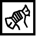
Remove, Disconnect Lever out retaining clips for injectors (arrow) and remove injector from fuel distributor pipe (see illus. I).
 Install, Connect Install, Connect Fit injection valves. Coat seal rings thinly with silicone grease (white). Insert retaining clips (arrows, see illus. II). Insert injectors together with fuel distributor pipe in lower part of intake manifold - 8 Nm / 6 lbf. ft.
Important! The injectors must always remain in a exactly defined installation position. Turning about the longitudinal axis leads to inferior exhaust gas emission values. In order to fix injectors in the optimum position, sheet metal tabs are fitted to the fuel distributor pipe adjacent to each injector, which permit only one installation position (see illus. III). | 
|
Install, Connect Attach fuel feed line to fuel distributor pipe and fuel return line as well as vacuum hose to fuel pressure regulator. Connect wiring harness plugs to injectors. Attach bracket for injector wiring harness plugs together with alternator shackle to lower part of intake manifold (arrow). Connect wiring harness plugs for injectors (1). Clip wiring harness plug for camshaft pulse pick-up (2) into bracket. Insert wiring harness plug for inductive pulse pick-up (3) into bracket and connect. Connect vacuum hose (4) to fuel pressure regulator. Attach upper part of intake manifold to lower part of intake manifold and to cylinder head cover with new gasket. Attach connection hose to throttle body. Connect all disconnected hoses to upper part of intake manifold.
 Tighten (Torque) Tighten (Torque) Upper part of intake manifold to lower part of intake manifold and to cylinder head cover - 8 Nm / 6 lbf. ft. | 
|
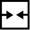
Install, Connect Push tank vent valve from above into bracket and insert retaining clips (see illus.). | 
|
Install ignition cable cover - insert retaining lugs of ignition cable cover into rubber shackles (2) and screw in fastening bolts (1).
Tighten (Torque) Attach ignition cable cover to upper part of intake manifold - 8 Nm / 6 lbf. ft. | 
|
|
