Camshaft and Cam Followers, Remove and Install
 Remove, Disconnect Remove, Disconnect Disconnect ground cable from battery. Remove air filter housing complete with air duct pipe and air intake hose. On C 14 SE, additionally disconnect wiring harness plug from intake air temperature sensor. Release V-belt or ribbed V-belt tension and remove - see corresponding operation. Remove flywheel cover. Lock flywheel with KM-517-B. Vehicles with aluminium oil pan, use KM-911 (before installing KM-911, remove plug; reinsert plug after removing tool). Remove V-belt pulley or increment disc from crankshaft. Remove upper and lower toothed belt cover (see illus. I). Turn crankshaft by hand and bring all pistons into centre position - 90 ° CA BTDC (see illus. II). | 
|
Remove, Disconnect Move toothed belt tension roller (1) upwards against spring force, until bore holes in moveable part of tension roller (3) and in the tension roller base plate (2) align. Fix toothed belt tension roller in position with suitable drift (arrow). Remove released toothed belt. Unbolt camshaft pulley -for this, counterhold camshaft at special lug between 1st and 2nd cylinders. Remove ignition distributor - see operation "Ignition Distributor, Remove and Install". For X 12 SZ, X 14 SZ and C 14 SE engines, remove DIS ignition module and underlying support plate - see corresponding operation. | 
|
Remove, Disconnect Remove camshaft. Screw commercially available valve lifter depressor onto camshaft housing and press down all cam followers uniformly.
 Important! Important! To avoid damage to thread in camshaft housing, use bolts of an adequate length. | 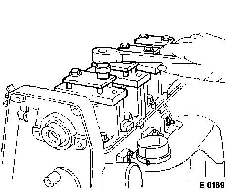
|
Remove, Disconnect Unbolt thrust plate for camshaft from distributor side and remove camshaft from camshaft housing on this side. Vehicles with ABS: remove hydraulic modulator - see corresponding operation in group H. | 
|
Remove, Disconnect Release valve lifter depressor uniformly and remove from camshaft housing cover. Remove cam followers and thrust pieces from camshaft housing.
Important! If the same parts are to be reinstalled, lay them aside so that their installation positions do not get mixed up. If the camshaft is being replaced, install new cam followers and thrust pieces.
 Inspect Inspect | 
|
Check all removed parts for damage and wear - replace if necessary.
 Install, Connect Install, Connect Coat rocker arm and thrust pieces with MoS 2 lubricating paste (grey) and insert into camshaft housing. Position valve depressor and tension all rocker arms uniformly. |
|
Install, Connect Slide camshaft with thrust plate into camshaft housing and bolt on thrust plate - tightening torque 8 Nm / 6 lbf. ft. For vehicles with ABS: Install hydraulic modulator - see corresponding operation in group "H". |
|
Remove, Disconnect Release valve lifter depressor uniformly and unbolt from camshaft housing.
Install, Connect Install new camshaft seal ring - see operation "Seal Ring in Front Camshaft Housing, Replace". Attach camshaft pulley to camshaft - 45 Nm / 33 lbf. ft. | 
|
Install, Connect Install ignition distributor, or DIS ignition module and support plate with new seal rings - see corresponding operation.
 Adjust Adjust Adjust timing and install toothed belt - see operation "Timing, Check and Adjust". | 
|
Install, Connect Install upper and lower toothed belt cover and V-belt pulley or increment disc. Counterhold flywheel with KM-517-B. Vehicles with aluminium oil pan, use KM-911.
 Torque - Angle Method Torque - Angle Method
|
Upper and lower toothed belt cover to rear toothed belt cover |
- 4 Nm / 3 lbf. ft. |
|
Crankshaft pulley/increment disc with toothed belt drive pulley to crankshaft (M 12) |
- 95 Nm / 70 lbf. ft. +30 ° + 15 ° 1) |
Install, Connect Install camshaft housing cover with new gasket and flywheel cover plate.
 Tighten (Torque) Tighten (Torque)
|
Camshaft housing cover to camshaft housing |
- 8 Nm / 6 lbf. ft. |
|
Flywheel cover plate to transmission |
- 7 Nm / 5 lbf. ft. |
| 
|
Install, Connect Install V-belt or ribbed V-belt - see corresponding operation.
Inspect For 12 NZ, C 12 NZ, C 14 NZ engines, check ignition adjustment, carry out ignition basic adjustment if necessary - see corresponding operation. | 
|
|
