Engine with Transmission, Remove and Install Operation described for C 14 SE engine - proceed analogously for other engines.
 Remove, Disconnect Remove, Disconnect Disconnect ground cable from battery. RHD vehicles: remove battery. Remove air cleaner housing with air intake hose. | 
|
Depressurise cooling system by opening closure cover of coolant compensation tank. Disconnect left coolant hose, right coolant hose and hose to coolant compensation tank. Collect escaping coolant. | 
|
Remove, Disconnect Disconnect wiring harness plug from fan motor, disconnect wiring harness from radiator fan shroud. Unbolt radiator fan shroud from radiator, pull out of bracket and remove upwards (arrows). | 
|
Disconnect Bowden cable from linkage lever (2) and from bracket (1) and set aside. Detach vacuum hoses from throttle body. Detach vacuum hose from brake servo. | 
|
Remove, Disconnect Remove wiring harness plugs from injectors (see illus. I). Disconnect cables ties. Set wiring harness aside. Remove coolant hoses from coolant compensation tank. Remove coolant compensation tank. Close off heating hoses with commercially available hose clamps and remove from connection on bulkhead (see illus. II, arrows). Remove clip from clutch cable and detach cable (see illus. III). Remove wiring plug connection from reversing lamps switch. | 
|
Remove, Disconnect Mark fuel feed and return hoses and close off with commercially available hose clamps. Unbolt bracket for fuel hoses at intake manifold (arrow) and remove fuel hoses from pipes on fuel distributor pipe. | 
|
Up to MY '95: Unscrew speedometer cable (arrow) from transmission - for this engage 2nd or 4th gear. For vehicles as of MY '96: detach speedometer cable in engine compartment. For vehicles as of MY '98: detach wiring harness plug from odometer signal sensor. Disconnect and mark all wiring plug connections leading to engine. Disconnect cable connections from alternator and starter. | 
|
Remove, Disconnect Vehicles with power steering: Release ribbed V-belt and remove. Unbolt power steering pump from bracket on cylinder block (arrows).
 Important! Important! System remains closed. | 
|
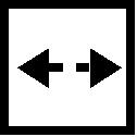
Remove, Disconnect Mark positions of front wheels to wheel hub and remove front wheels. Loosen shift rod clamp (arrow) and remove shift rod from transmission shift linkage. | 
|
Remove, Disconnect Unbolt exhaust system from exhaust manifold, detach from retaining rubbers and swing aside. | 
|
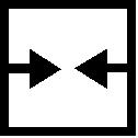
Unbolt steering knuckle/guide joint clamp bolts and remove guide joints from steering knuckle. Unbolt front suspension control arms from body (arrows). | 
|
Remove, Disconnect Unbolt tie struts bracket from crossmember (arrows) and remove with control arm, front suspension and stabiliser. | 
|
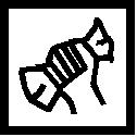
Drive left and right axle shafts with KM-460-B (or use KM-902 for both left and right axle shafts) out of transmission housing and tie up axle shafts. Chamfered side of tool points towards transmission. To prevent loss of transmission fluid, close off transmission openings for axle shafts with plugs. | 
|
 Install, Connect Install, Connect Attach bracket for KM-6054 to cylinder block. Attach Base Frame KM-904 with KM-6054 on hydraulic jack and position under the drive unit. Notice: To ensure correct alignment of the drive unit after the engine damping blocks have been released, the drive unit must be aligned with the body using KM-6054. The attachment of KM-6054 is described below.
Install, Connect Twist strut bearing retaining plate (4) upwards until retaining plate bears flush against the transmission. Twist strut bearing (6) upwards until pin bears flush against flattened area (5) of cylinder block. Twist strut bearing (7) upwards until pin bears flush in mount of bracket (8). Twist strut bearing (2) upwards until pin lies flush in mount of flattened area (1). Twist strut bearing (3) upwards until pin lies flush in mount of flattened area of cylinder block on transmission side. Lift drive unit slightly with KM-6054. | 
|
Remove, Disconnect Unbolt engine damping blocks from front frame side member and vehicle floor. Move drive unit downwards out of engine compartment with KM-6054.
 Clean Clean Recut bolt and thread in front frame side member to remove residual locking compound.
Install, Connect Move drive unit into engine compartment from below with KM-6054 and secure engine damping blocks - see corresponding operations.
Remove, Disconnect Move hydraulic jack downwards and remove Base Frame KM-904 with KM-6054 from hydraulic jack. Remove bracket for KM-6054 from cylinder block.
Install, Connect Press both axle shafts into transmission housing until they engage.
 Inspect Inspect Check that axle shafts are firmly seated by pulling on joint - see illus. | 
|
Install, Connect Insert guide joints into steering knuckle. Install control arms and tie struts with stabilisers.
 Torque - Angle Method Torque - Angle Method
|
Guide joint to steering knuckle |
30 Nm / 22 lbf. ft. 1) |
|
Front suspension control arm to body |
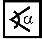
45 Nm / 33 lbf. ft. + 45 ° + 15 ° |
|
Tension strut bracket to crossmember |
50 Nm / 37 lbf. ft. + 90 ° + 15 ° 2) |
1) Use new fastening nut(s). 2) Use new fastening bolts.
Install, Connect |
|
Connect electrical connecting cables for alternator and starter. Attach exhaust system to retaining rubbers and bolt to exhaust manifold with new gasket (see illus.).
 Tighten (Torque) Tighten (Torque) Exhaust pipe to exhaust manifold - 25 Nm / 18 lbf. ft. |
|
Install, Connect Push shift rod into linkage.
 Adjust Adjust Adjust shift linkage - see operation "Transmission Shift Linkage, Adjust" in group K.
Install, Connect |
|
For vehicles up to MY '95: attach speedometer cable to transmission - for this purpose engage 2nd or 4th gear. For vehicles as of MY '96: attach speedometer cable in engine compartment. For vehicles as of MY '98: attach wiring harness plug to odometer signal sensor. Attach clutch cable and connect clip. Attach heating hoses to connections on bulkhead (arrows) and fasten. Remove hose clamps. | 
|
Install, Connect Attach fuel hoses and remove commercially available hose clamps. Fasten fuel hoses with bracket to intake manifold (see illus.). Connect vacuum hoses. Connect brake servo vacuum hose. | 
|
Fasten coolant hoses to coolant compensation tank and fasten tank to bulkhead. Connect engine wiring harness plug connections. Connect temperature sensor, oil pressure switch and reversing lamps. Connect wiring harness plugs to injectors, fasten wiring harness. Attach accelerator Bowden cable and adjust. | 
|
Install, Connect Insert radiator fan shroud in lower brackets on radiator and fasten. Connect wiring plug connections to fan motor (1) and fan motor temperature switch (2). Fasten wiring harness. Connect oxygen sensor wiring plug connection.
Important! Route wiring harness so that it cannot be damaged by fan gear.
Install, Connect | 
|
Install upper and lower coolant hoses. Install air intake hose and air cleaner housing. |
|
Install, Connect Vehicles with power steering: fasten power steering pump to bracket. Install ribbed V-belt. Connect ground cable to battery. RHD: install battery. | 
|
Top up coolant in compensation tank and bleed cooling system - see corresponding operation. Ensure that anti-freeze is adequate down to -30 ° C / -22 ° F.
Inspect Allow engine to cool and check coolant level, correct if necessary (see illus.). Check transmission fluid level, correct if necessary. | 
|
|
