
Corsa B
Field Remedy: 1268
Remedy:General: Remove the alternator according to the Service Instructions. Installation of new diode plate must be performed according to the following instructions. Important! · Replacement of rectifier bridge may be carried out only by specialists with corresponding prior knowledge in soldering and in compliance with greatest care. · Replacement of rectifier bridge is to be performed exclusively by using a High-Quality soldering device. · Soldering operations should only be carried out by using solder metal corresponding to the following specification: "ASTM-B-32- 93" solder metal 96.5/ 3.5 Tin/Silver. · Apply only enough heat as necessary during the desolder and solder operations as to complete the operation. Excessive heat (time applied) may damage diodes. In addition, excessive amounts of solder may cause stator shorts. Procedure: 1. Remove alternator according to the Service-Instructions. 2. Clamp alternator in a vice. Disassembly: 3. Loosen bolts from housing cover (1, see illus. I), remove housing cover from alternator. 4.Unscrew capacitor from housing cover (2, see illus. II). 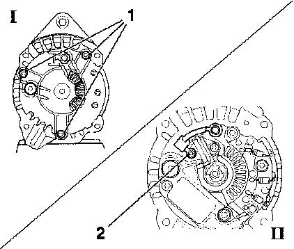
Important! Do not damage carbon brushes and slip rings when removing brush holder! Disassembly: 5. Disconnect plug connection between brush holder and electronic regulator (see illus.I). 6. Remove bolt from brush holder (1, see illus. II). 7. Lift carbon brushes from slip rings (see illus. III) and remove brush holder from housing. 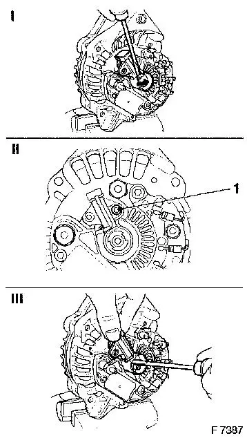
Disassembly: 8. Remove bolts from electronic regulator (1, see illus. I). Note different types of bolts! Important! · To prevent solder outstandings droppping into alternator, all soldering operations must be carried out in a vertical position. Alternator has to be placed exactly in position as shown in the illustration. · To prevent overheating of the diodes when unsoldering, hold connection cable with flat-nosed pliers - this conducts the heat away (see illus. II). 9. Solder off connection between electronic regulator and rectifier bridge. Remove electronic regulator. 10.Remove bolts from rectifier bridge (2, see illus. III). 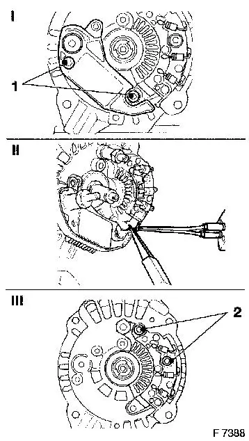
Important! · To prevent solder outstandings dropping into alternator, all soldering operations must be carried out in a vertical position. Alternator has to be placed exactly in position as shown in the illustration. · To prevent overheating of the diodes when unsoldering, hold connection cable with flat-nosed pliers - this conducts the heat away (see illus. II). Disassembly: 11. Solder off rectifier bridge from stator winding. 12. Remove rectifier bridge. 13. Remove remainder of old heat conduction paste completely. 14. Do not remove insulation from winding ends. 15. Do not disassemble alternator housing. 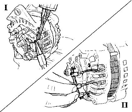
Assembly: 1.Evenly apply white thermal grease to alternator rectifier bridge mounting surface. 2.Place bridge assembly onto locators. 3.Place regulator into position. 4. Hand place bridge/regulator screw (insulated, bronze color). 5. Hand place other two bridge screws (silver with captured washer). 6. Tighten the four M4 torx screws in a progressive circular pattern until proper torque is reached. Torque the insulated bridge regulator screw to 3 Nm.
Torque other screws to 3 Nm.
7. Crimp three bridge phase terminals around stator leads.
8. Crimp bridge phase terminal to regulator lead.
9. Solder three stator leads and regulator phase lead to bridge
   terminals.
Important! · To avoid mechanical stress beeing applied to diodes while crimping the connection between winding ends and rectifier bridge, the diode contact tabs must be fixed in central position by flat-nosed pliers. · To prevent solder outstandings dropping into alternator, all soldering operations must be carried out in a vertical position. Alternator has to be placed exactly in position as shown in the illustration. · Use approved solder metal 96.5/ 3.5 Tin/ Silver only! · To prevent overheating of the diodes when soldering, hold connection cable with flat-nosed pliers - this conducts the heat away (see illus. II). · Apply only enough heat as necessary during the desolder and solder operations as to complete the operation. Excessive heat (time applied) may damage diodes. In addition, excessive amounts of solder may cause stator shorts. 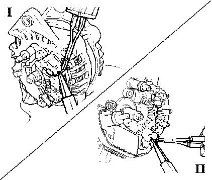
Assembly: 10. Lift carbon brushes during installation of brush holder with
suitable tool (see illus. I).
11. Install brush holder to housing (1, see illus. II).
Important! · Do not damage carbon brushes and slip ring when installing brush holder! · Make sure that Carbon brushes fit well!
12. Fit plug connection between brush holder and electronic
    regulator (see illus. III).
13. Place capacitor on terminal B+30 (2) and attach to brush
    holder (3) (see illus. IV).
14. Install rear housing cover.
Marking: All affected vehicles which have been reworked according to this information must be clearly marked by a white dot on the top of the alternator housing. 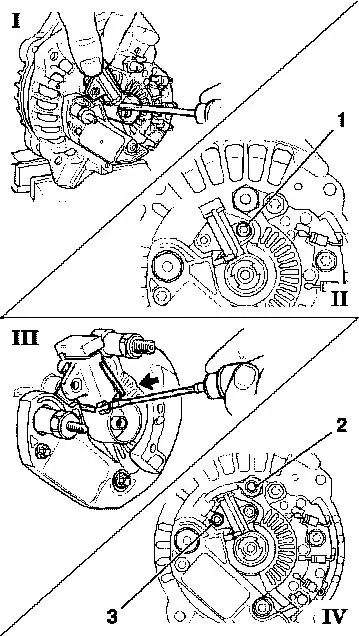
Parts:                             Part-No.:        Cat.-No.:
Diode Plate                        10 45 08 17      12 05 433
Labor-Times: Description Model Engine TC: Hours:
T8 126 80 Replace diode Corsa-B/ C14NZ 92 1.0 hrs
plate Tigra C14SE
X14SZ
                                             X14SEL       1.7 hrs
                                             X14XE
                                             C16SEL
                                             C16XE
                                             X16XE
       001     Additional work                            0.1 hrs
               at cars with lower
               engine cover
       002     Additional work                            0.5 hrs
               at cars with A/C
T8 126 81      Replace diode        Astra-F   X14NZ  92   0.9 hrs
               plate                           16LZ2
                                              C16SE
                                              X16SZR
X14XE 1.2 hrs X16XEL 1.8 hrs
X17DTL 1.5 hrs
The regular warranty procedure should be used for claiming Set-up-time
|
||||||||||||||||||||