|
Anti-lock braking system (ABS 8.0 and ABS 8.0
ESP)
General
From MY 2004, the Corsa-C, in all engine variants, will be
fitted with the new anti-lock braking system, ABS 8.0.
ABS 8.0 is a modular system, with 8 solenoid valves. In its
basic form it is the same as ABS 5.3 and is also available with ESP
as an option.
With the introduction of ABS 8.0 ESP, Opel vehicles will, for
the first time, be taking the "braking system temperature"
parameter into account in the braking system control strategy.
By measuring the temperature in the hydraulic unit, a map can be
calculated to determine whether there is a risk of the braking
system overheating, for example, on downhill runs.
The ABS control unit/hydraulic unit assembly has been modified.
The weight of the ABS control unit/hydraulic unit has been reduced
by 25% by using modern microprocessor technology. At the same time,
the exterior dimensions have been changed, thus reducing the volume
of the assembly by 30% compared with ABS 5.3.
Thanks to its horizontal installation position in the Corsa-C,
the ABS control unit can be detached from the hydraulic unit whilst
still installed.
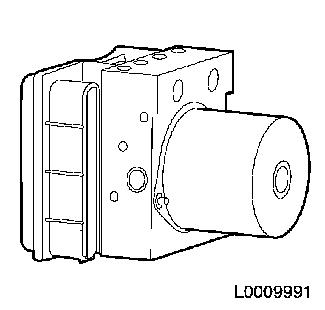
ABS control unit/hydraulic unit assembly
|
| 1. |
ABS control unit |
| 2. |
Hydraulic unit |
|
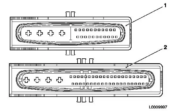
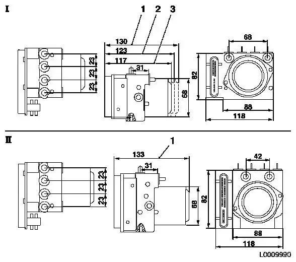
From an appearance point of view, the ABS 8.0 and ABS 8.0/ESP do
not just differ in size.
The diameter of the hydraulic connections on the ABS control
unit coming from the master cylinder is smaller on the ABS 8.0 than
on the ABS 8.0/ESP.
The electrical connection on the ABS control unit is a 26-pin
connection on the ABS 8.0 and a 46-pin connection on the ABS
8.0/ESP.
Dimensions and weight
The weight of the ABS 8.0 also varies depending on the
version.
| |
ABS 8.0 (XS engine)
|
ABS 5.3
|
|
Dimensions
|
|
|
|
Width x height x length
|
(118 x 80.3 x 113.6) mm
|
(84 x 118 x 170) mm
|
|
Volume
|
1.1 litres
|
1.7 litres
|
|
Weight
|
1.6 kg
|
2.6 kg
|
| |
ESP 8.0/ESP (S/L engine)
|
ABS 5.3 TCS/ESP
|
|
Dimensions
|
|
|
|
Width x height x length
|
118 x 103 x 132.5) mm
|
84 x 138 x 183 mm
|
|
Volume
|
1.7 litres
|
2.1 litres
|
|
Weight
|
2.3 kg
|
3.2 kg
|
|
|
Versions
|
1
|
L engine
|
3
|
XS engine
|
|
2
|
S engine
|
4
|
L engine
|
|
Installation location
|
The ABS control unit/hydraulic unit assembly is installed
horizontally (1) in the Corsa-C. The motor of the hydraulic unit is
installed with its shaft in a horizontal position and the
connections of the individual brake circuits face upwards. The
advantage of this installation position is that the ABS control
unit can be removed for assembly or repair work without having to
remove the entire assembly.
|
|
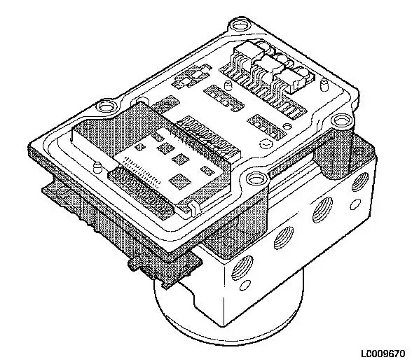
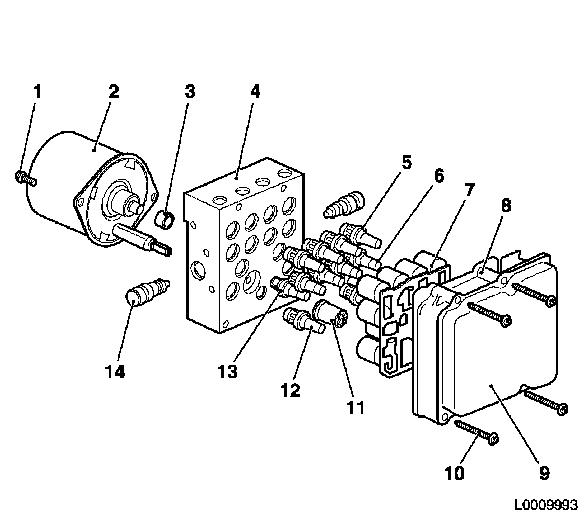
Exploded diagram
|
|
1
|
Pump motor fastening bolt (x2)
|
8
|
ABS control unit
|
|
2
|
Pump motor
|
9
|
ABS control unit cover
|
|
3
|
Guide sleeve
|
10
|
ABS control unit fastening bolt (x4)
|
|
4
|
Pump/valve housing
|
11
|
Pressure sensor (only ABS 8.0/ESP)
|
|
5
|
Outlet valves (x4)
|
12
|
USV valve (x2)
|
|
6
|
Inlet valves (x4)
|
13
|
ASV/HSV valve (x2)
|
|
7
|
Printed circuit board with semiconductor relay
|
14
|
Pressure control valve (x2)
|
|
|
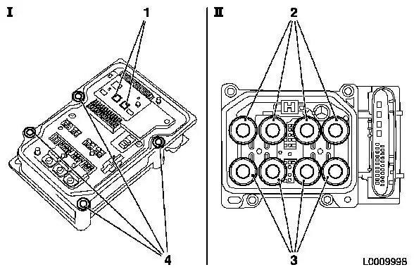
ABS control unit
|
|
|
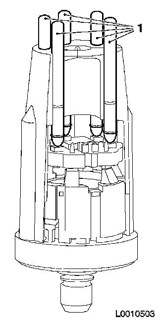
The control unit of the ABS 8.0 is based on the latest pulse
line and chip technology and is designed to connect to 4 active or
4 passive wheel sensors. Active wheel sensors are used on the
Corsa-C. The regulation and control function of ABS 8.0 is
safeguarded by two separate microprocessors (1). Each of these
microprocessors can be reprogrammed. The individual components of
the ABS control unit are not replaceable. If there is a fault, the
entire ABS control unit has to be replaced.
The pump motor in the hydraulic unit of ABS 8.0 is actuated via
the pump housing. The solenoid valves to the hydraulic unit are
actuated by magnet coils. These magnet coils are connected directly
with the semiconductor relay in the ABS control unit and are
therefore incorporated into the ABS control unit.
The ABS control unit is connected to the hydraulic unit via four
fastening bolts (4) and can be detached and removed from the
hydraulic unit in the vehicle.
|
• Service:
For repair work it is possible to replace the ABS control unit and
the hydraulic unit separately.
The hydraulic unit is supplied "pre-filled" from the Service
department. The seal of the ABS control unit is not available
separately. If there is a leak between the hydraulic unit and the
ABS control unit, the entire ABS control unit/hydraulic unit must
be replaced.
Conditions for replacing the ABS control unit:
- The ABS control unit should only be replaced with a new one if
the unambiguous diagnosis result "ABS control unit fault" (when
diagnosing with Tech 2 and error code "Faulty control unit" is
present) is obtained or if there is visible damage to the housing
or the connector of the ABS control unit.
- If the ABS control unit is detached from the hydraulic unit
whilst still in situ, ensure that the surrounding area is kept
clean as even the smallest amount of dirt in the hydraulic unit's
valves can cause malfunctions.
- Under no circumstances must the cover of the ABS control unit
be pushed in. This will cause damage to the ABS control unit that
will not be visible from the outside. When installing only hold the
ABS control unit on the outside edge of the housing. Do not use
force when installing the unit.
- Under no circumstances should the ABS control unit be attached
to the hydraulic unit with fastening screws. This will cause damage
to the ABS control unit and/or the hydraulic unit.
- The components of ABS 8.0, particularly in connection with the
ABS control unit/hydraulic unit assembly, should only be replaced
by specialist personnel with the appropriate specialist knowledge
of the conditions for replacement and the Service Instruction.
- Only the new parts specified in the electronic parts catalogue
should be used as replacement parts.
Hydraulic unit
When installed, the hydraulic unit is connected with the ABS
control unit. On the version with ESP, the pressure sensor is no
longer on the outside of the hydraulic unit, like on ABS 5.3 TC/ESP
but instead is incorporated into the hydraulic unit. The individual
components of the hydraulic unit cannot be replaced or repaired. If
there is a fault, either the entire hydraulic unit or the entire
ABS control unit/hydraulic unit assembly has to be replaced.
The hydraulic unit's hydraulic connections to the master
cylinder are spaced differently for the ABS 8.0 and ABS 8.0/ESP
versions. The diameters of the hydraulic connections also differ on
the two versions. It is therefore impossible to install the wrong
version of the hydraulic unit.
The spring contact pins located on the side facing the ABS
control unit must not be touched because of possible electrostatic
discharge. Neither should measurements be taken at them. The spring
contact pins cannot be replaced separately. Likewise, to prevent
damage, the hard gold surface of the contact pins should not be
mechanically machined or treated with liquids such as contact
spray.
No measurements should be taken at the connector contacts for
the pump motor either. The contacts cannot be replaced and are led
in the lower section of the hydraulic unit through the valve block
to the ABS control unit.
Pressure and temperature sensor - ABS 8.0 ESP
|
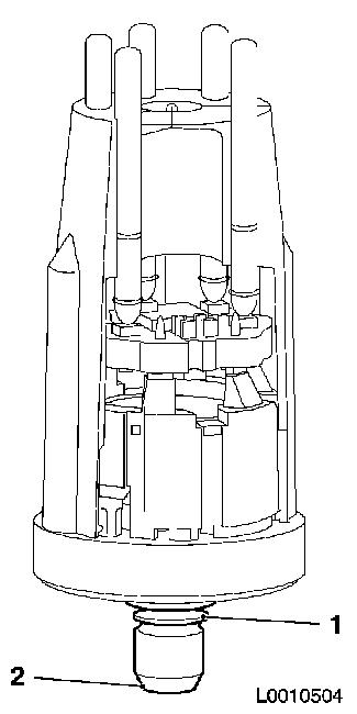
Unlike on the ABS 5.3 TC/ESP, the pressure sensor on the ABS 8.0
ESP is no longer on the outside of the hydraulic unit, but
incorporated into the hydraulic unit instead. The electrical
connection to the ABS control unit is achieved using gold coated
spring contact pins. The pressure sensor is attached to the
hydraulic unit using a self-locking mechanism (1) and cannot be
removed. The sensor is sealed off by means of the conical surface
(2).
The pressure sensor also incorporates a temperature sensor. The
temperature sensor measures the temperature of the hydraulic unit.
This information is used in the ABS control unit to assess the load
on the braking system by means of characteristic curves. For
example, the system assesses whether the braking system is about to
overheat as a result of driving downhill. When driving downhill,
the braking process causes the brake discs to heat up so much that
the heat that is generated in the brake discs is transmitted via
the brake calliper to the brake fluid. As a result, the temperature
in the hydraulic unit rises as well.
|
|
The pressure and temperature sensor has the following properties
for all ABS control units:
- Selftest function
- Full self-diagnosis function with detection of sensitivity and
offset errors
- 2 analogue outputs for pressure
- 2 digital outputs for temperature
Technical data for the pressure sensor
|
Pressure sensor measuring range:
|
(0 ... 250) bar
|
|
Temperature sensor measuring range
|
(-40 ...+120) °C
|
|
Power supply:
|
5 V DC
|
|
• Service:
The pressure sensor cannot be replaced individually. Like the
spring contacts (1), the contact plate for the pressure sensor in
the ABS control unit has a hard gold surface. It must not be
mechanically machined.
The position of the pressure sensor must not be changed (e.g. by
twisting). Neither should the sensor housing be subjected to
mechanical loads, otherwise non-visible damage may occur. If there
is a fault with the pressure sensor (apart from leaks), the entire
hydraulic unit must be replaced. If there are still faults with the
pressure sensor when the system goes back into operation, the ABS
control unit will have to be replaced as well.
If there is evidence of brake fluid loss at the pressure sensor,
the entire ABS control unit/hydraulic unit assembly will have to be
replaced as damage to the ABS control unit by brake fluid can no
longer be ruled out in this case.
|
|
ABS control unit wiring harness plug
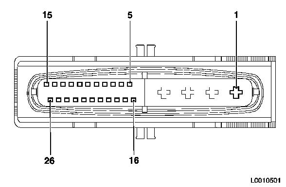
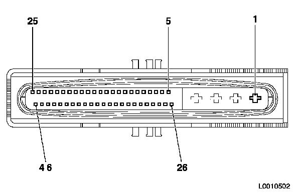
The plug connection on the ABS control unit is a 26-pin
connector (1) for the ABS 8.0 and a 46-pin connector (2) for the
ABS 8.0 ESP. For both variants, the wiring harness connector
contains 4 power contacts with individual core seal. The size of
the power contacts is (2.8 x 0.8) mm.
ABS 8.0 also has 22 signal contacts (42 for ABS 8.0 ESP), size
(0.63 x 0.63) mm. The signal contacts are protected in the ABS
control unit connector by a silicon seal.
After connecting them. the wiring harness connectors are locked
by inserting the plastic pin.
|
Pin assignment - ABS control unit for ABS 8.0
|
|
|
Pin
|
Assignment
|
Pin
|
Assignment
|
|
1
|
Earth
|
14
|
Engine control unit
|
|
2
|
Battery + (terminal 30)
|
15
|
CAN bus:
With MTA: Signal line to MTA
Without MTA: Signal line to BCM
|
|
3
|
Battery + (terminal 30)
|
16
|
Not assigned
|
|
4
|
Earth
|
17
|
Rear left wheel sensor
|
|
5
|
Front right wheel sensor
|
18
|
Ignition + (terminal 15)
|
|
6
|
Front right wheel sensor
|
19
|
Rear right wheel sensor
|
|
7
|
Rear left wheel sensor
|
20
|
Brake light switch
|
|
8
|
Rear right wheel sensor
|
21
|
Not assigned
|
|
9
|
Front left wheel sensor
|
22
|
Body Control Module (BCM, CAN bus)
|
|
10
|
Front left wheel sensor
|
23
|
Instrument cluster
|
|
11
|
Diagnostics connector
|
24
|
Not assigned
|
|
12
|
Not assigned
|
25
|
Engine control unit
|
|
13
|
Not assigned
|
26
|
CAN bus:
With MTA: Signal line to MTA
Without MTA: Signal line to BCM
|
|
|
Pin assignment - ABS control unit for ABS 8.0
ESP
|
|
|
|
|
Pin
|
Assignment
|
Pin
|
Assignment
|
|
1
|
Earth
|
24
|
Not assigned
|
|
2
|
Battery + (terminal 30)
|
25
|
CAN bus:
Signal line - yaw rate and steering angle
sensor
Also:
With MTA: MTA signal line
Without MTA: BCM signal line
|
|
3
|
Battery + (terminal 30)
|
26
|
Not assigned
|
|
4
|
Earth
|
27
|
Rear left wheel sensor
|
|
5
|
Front right wheel sensor
|
28
|
Ignition + (terminal 15)
|
|
6
|
Front right wheel sensor
|
29
|
Rear right wheel sensor
|
|
7
|
Rear left wheel sensor
|
30
|
Brake light switch
|
|
8
|
Rear right wheel sensor
|
31
|
Not assigned
|
|
9
|
Front left wheel sensor
|
32
|
Body Control Module (BCM, CAN bus)
|
|
10
|
Front left wheel sensor
|
33
|
Not assigned
|
|
11
|
Diagnostics connector
|
34
|
Not assigned
|
|
12
|
Not assigned
|
35
|
Engine control unit
|
|
13
|
Not assigned
|
36
|
Not assigned
|
|
14
|
Engine control unit
|
37
|
Not assigned
|
|
15
|
Not assigned
|
38
|
Not assigned
|
|
16
|
Not assigned
|
39
|
Not assigned
|
|
17
|
Not assigned
|
40
|
Not assigned
|
|
18
|
Not assigned
|
41
|
Not assigned
|
|
19
|
Not assigned
|
42
|
Instrument cluster
|
|
20
|
Not assigned
|
43
|
Not assigned
|
|
21
|
Not assigned
|
44
|
Not assigned
|
|
22
|
Not assigned
|
45
|
CAN bus:
Signal line - yaw rate and steering angle
sensor
Also:
With MTA: MTA signal line
Without MTA: BCM signal line
|
|
23
|
Not assigned
|
46
|
Not assigned
|
|
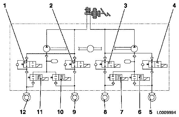
Hydraulic system diagram - ABS 8.0
|
|
|
1
|
Front right inlet valve
|
7
|
Rear right outlet valve
|
|
2
|
Rear left inlet valve
|
8
|
Rear right brake
|
|
3
|
Rear right inlet valve
|
9
|
Rear left brake
|
|
4
|
Front left inlet valve
|
10
|
Rear left outlet valve
|
|
5
|
Front left brake
|
11
|
Front right outlet valve
|
|
6
|
Front left outlet valve
|
12
|
Front right brake
|
|
Bleeding the ABS 8.0 and ABS 8.0 ESP braking
systems
Like on the Astra-G, the ABS 8.0 hydraulic system is bled in the
following sequence: rear right, rear left, front right, front left.
The brake bleeding equipment available from the "Service"
department must be used for this purpose.
The brake fluid goes into the reservoir and is pushed by the
admission pressure of the brake bleeding equipment through the
master cylinder and the hydraulic unit into the wheel brake
cylinder. The bleed screw of the brake circuit being bled (here the
front left circuit) is opened. All other bleed screws are
closed.
While the brakes are being bled, the initial pressure can be
boosted, thereby improving results, by operating the pedal. The
respective brake circuits must be bled until the brake fluid comes
out without any bubbles or foam. The bleed operation is repeated in
the same way on the other 3 wheels.
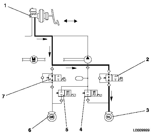
The following hydraulic diagram of the ABS 8.0
shows a normal bleed operation being carried out on the front left
brake circuit.
|
|
1
|
Master cylinder
|
5
|
Rear right outlet valve
|
|
2
|
Front left inlet valve
|
6
|
Rear right brake
|
|
3
|
Front left brake
|
7
|
Rear right inlet valve
|
|
4
|
Front left outlet valve
|
|
|
|
Electrical data
|
Software:
|
|
|
Repeat switch-on voltage after ignition ON
|
(9.7 ± 0.3) V
|
|
Undervoltage switch-off during regulation
|
(8.9...9.6) V
|
|
Undervoltage switch-off outside regulation period
|
(9.2 ... 9.9) V
|
|
Overvoltage switch-off
|
(16.8 ± 0.5)V
|
| |
|
|
Hardware:
|
|
|
Upper shut-off threshold
|
(19.9...23.5) V
|
|
Upper cut-in threshold
|
(20.7 ± 1.7) V
|
|
Lower shut-off threshold
|
(6.9...7.8) V
|
|
Lower switch-on threshold
|
(7.5 ± 0.4 V
|
| |
|
|
Overvoltage resistance of entire system
|
|
|
with ignition ON, no operation
|
< 18 V
|
|
Duration
|
1 h
|
|
at ambient temperature
|
(23 ± 5) °C
|
| |
|
|
Jump start of entire system
|
|
|
Overvoltage
|
< 24 V
|
|
Duration
|
5 min
|
|
at ambient temperature
|
(23 ± 5) °C
|
Hydraulic data
|
Pump delivery rate per circuit in ABS operation
|
|
| |
at a voltage at the pump motor of
|
(10 ± 0.1) V
|
| |
|
with pump motor XS
|
> 1.1 cm 3 /s
|
| |
|
with pump motor S
|
> 1.5 cm 3 /s
|
| |
|
with pump motor L
|
> 2.2 cm 3 /s
|
| |
|
|
|
| |
at a voltage at the pump motor of
|
(12 ± 0.1) V
|
| |
|
with pump motor XS
|
> 1.8 cm 3 /s
|
| |
|
with pump motor S
|
> 2.2 cm 3 /s
|
| |
|
with pump motor L
|
> 3.0 cm 3 /s
|
| |
|
|
|
|
Pressure data:
|
|
| |
Permissible operating pressure
|
<200 bar
|
| |
Maximum permissible pressure peaks during pump operation in
primary circuit
|
< 250 bar
|
| |
|
|
|
|
Minimum pressure up to outer leak in the
|
|
| |
primary circuit
|
350 bar
|
| |
Secondary circuit
|
150 bar
|
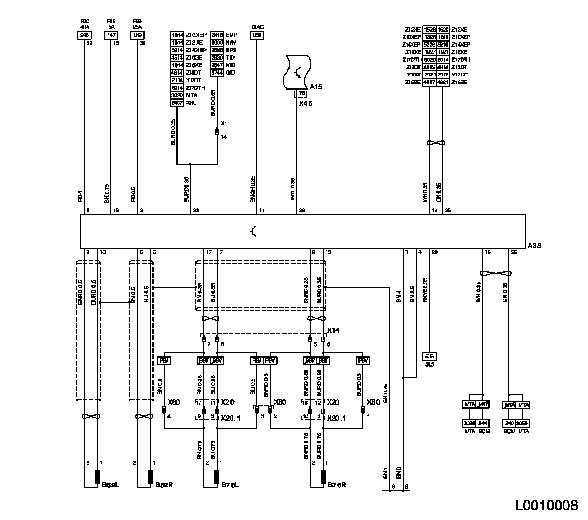
Wiring diagram - ABS 8.0
|
Component
|
Description
|
Component
|
Description
|
|
BCM
|
Bodywork Control Module
|
Control units
|
|
DIAG
|
Diagnostics connector
|
A15
|
Bodywork Control Module
|
|
ECC
|
Electronic climate control
|
A38
|
ABS control unit
|
|
EMP
|
Radio
|
Sensors
|
|
|
EPS
|
Electric power steering
|
B52L
|
Front left wheel speed sensor
|
|
GID
|
Graphic Info Display
|
B52R
|
Front right wheel speed sensor
|
|
MID
|
Multi Info Display
|
B76L
|
Rear left wheel speed sensor
|
|
MTA
|
Automatic-shift manual transmission
|
B76R
|
Rear right wheel speed sensor
|
|
NAV
|
Navigation system
|
Wiring harness connector
|
|
PBV
|
Corsa-C Combo
|
X1
|
Instrument panel and front body
|
|
SLS
|
Brake light switch
|
X14
|
Left-hand body
|
|
TID
|
Triple Info Display
|
X20
|
Rear left body
|
|
TM
|
Telematics
|
X20.1
|
Rear left body
|
|
WEG
|
Distance signal
|
X46
|
Front body and bodywork control module
|
|
XNL
|
Xenon headlamps
|
X80
|
Rear left body
|
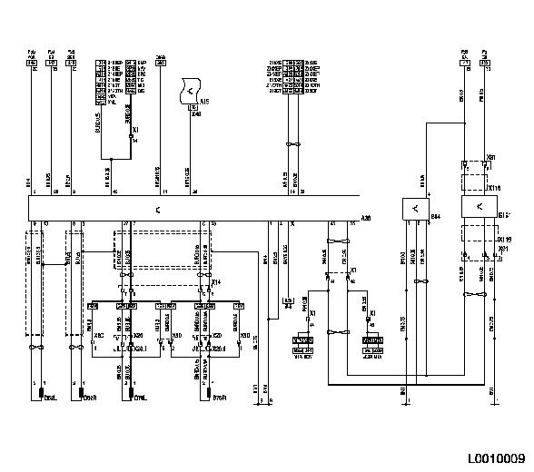
Wiring diagram - ABS 8.0 ESP
|
Component
|
Description
|
Component
|
Description
|
|
BCM
|
Bodywork Control Module
|
Sensors
|
|
DIAG
|
Diagnostics connector
|
B52L
|
Front left wheel speed sensor
|
|
EMP
|
Radio
|
B52R
|
Front right wheel speed sensor
|
|
EPS
|
Electric power steering
|
B76L
|
Rear left wheel speed sensor
|
|
GID
|
Graphic Info Display
|
B76R
|
Rear right wheel speed sensor
|
|
MID
|
Multi Info Display
|
B84
|
Yaw rate sensor
|
|
MTA
|
Automatic-shift manual transmission
|
B161
|
Steering angle sensor
|
|
NAV
|
Navigation system
|
Wiring harness connector
|
|
PBV
|
Corsa-C Combo
|
X1
|
Instrument panel and front body
|
|
SLS
|
Brake light switch
|
X14
|
Left-hand body
|
|
TID
|
Triple Info Display
|
X20
|
Rear left body
|
|
XNL
|
Xenon headlamps
|
X20.1
|
Rear left body
|
|
Control units
|
X46
|
Front body and bodywork control module
|
|
A15
|
Bodywork Control Module
|
X80
|
Rear left body
|
|
A38
|
ABS control unit
|
X91
|
Instrument panel and contact unit
|
| |
|
X116
|
Contact unit
|
| |
|
|
|
| |
|
|
|
|