|
Oil Pump, Remove and Install (Z 17 DTH, with AC,
LHD)
 Remove Remove
Important: In vehicles as of
model year 04 with ESP - every time the battery is disconnected,
the steering angle sensor loses its basic setting and must be
recalibrated
|
| 2. |
Disconnect battery
|
| 3. |
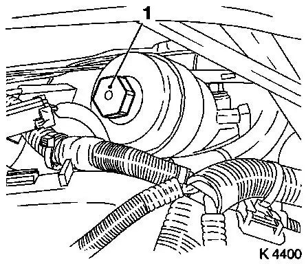
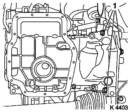
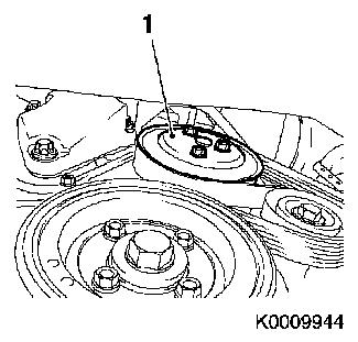
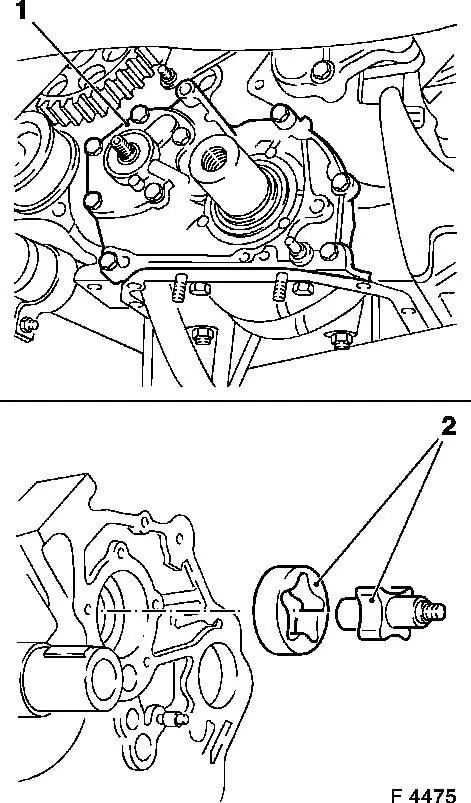
Remove oil filter element
| • |
Place collecting basin underneath.
|
| • |
Unscrew oil filter housing cover (1)
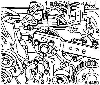
|
|
|
|
| 4. |
Remove oil dipstick guide tube
|
|
|
| 5. |
Detach front right wheel
|
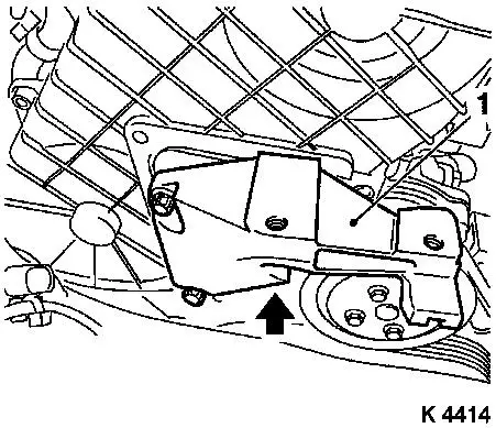
| 7. |
Remove right front wheel
|
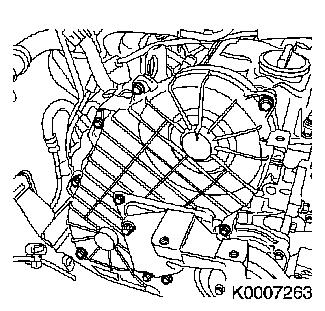
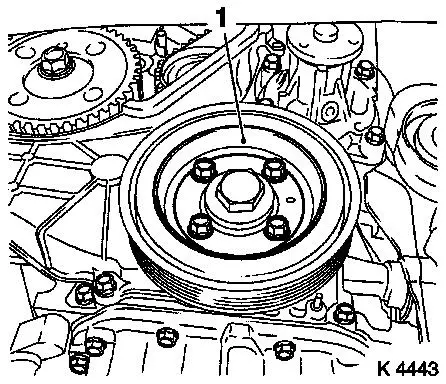
| 9. |
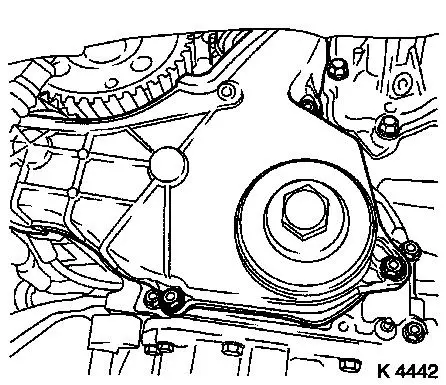
Remove ribbed V-belt cover
|
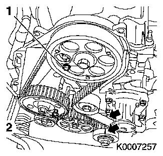
|
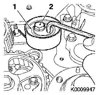
|
| 10. |
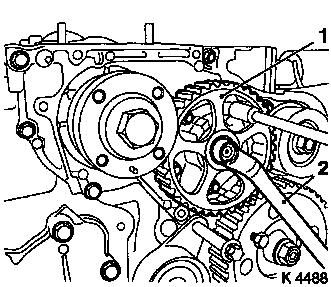
Drain engine oil
| • |
Place collecting basin underneath.
|
|
| 12. |
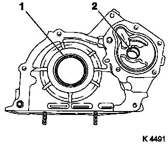
Remove front exhaust pipe
Note: When removing the
centre muffler, a catalytic converter, an exhaust manifold or
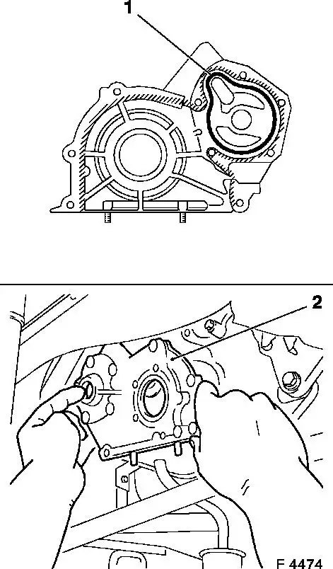
exhaust manifold with catalytic converter, the exhaust system piece
remaining in the vehicle must be secured to prevent it sagging
uncontrollably. The exhaust gas system piece with the flex pipe
inside it can be fastened to the vehicle underbody with suitable
materials such as e.g. wire.
|
| 13. |
Attach exhaust system
| • |
Attach retaining rubber (5x)
|
| • |
Tether exhaust system laterally
Note: Second person
required
|
|
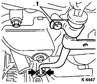
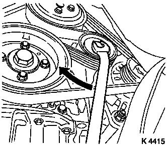
| 14. |
Remove oil dipstick guide tube
| • |
Unscrew 2 bolts (arrows)
|
|
|
|
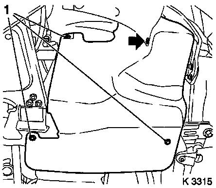
| 15. |
Detach oil pan lower part
|
|
|
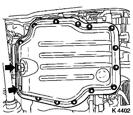
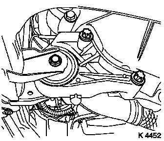
| 16. |
Remove front reaction member
|
|
|
| 17. |
Detach oil pan upper part
| • |
Disconnect dynamic oil level check wiring harness plug
|
| • |
Unscrew 14 bolts
Note: Note dissimilar
bolt lengths
|
| • |
Undo intermediate shaft bearing support
|
|
|
|
| 18. |
Attach front reaction member
|
| 19. |
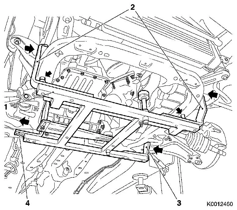
Attach KM-6394
| • |
Position KM-6394 (1) at the front on
the front axle body
Note: Both locating
pins (arrows) must be seated in the holes in the front axle
body
|
| • |
Push front bracket (2) in the direction of the arrow
|
| • |
Place rear bracket (4), right hand side, on front axle body
|
| • |
Attach rear bracket (3), left hand side
|
|
|
|
|
| 20. |
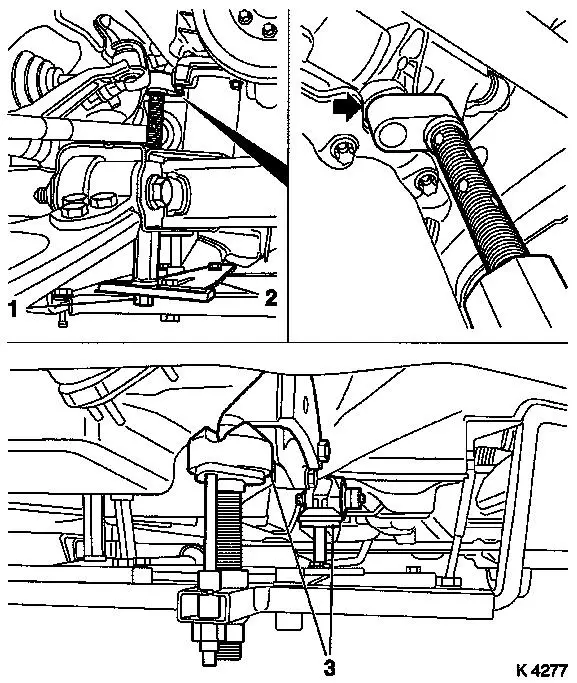
Install support
| • |
On KM-6394
| – |
Adjust bracket (2) for support
|
|
|
| 21. |
Adjust 3x support
| • |
Transmission side
Note: Turn spindles
until mounts (3) are positioned at guide journals free of play
|
| • |
Engine timing side
| – |
Insert journal of the support in the bore of the cylinder block
free of play (arrow)
|
|
|
|
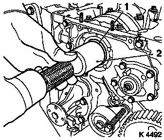
| 22. |
Loosen coolant pump ribbed V-belt pulley (1)
|
|
|
| 23. |
Remove ribbed V-belt
| • |
Tension ribbed V-belt tensioner in direction of arrow
| – |
Use KM-913-A
Note: Mark running
direction.
|
|
|
|
|
| 24. |
Detach coolant pump ribbed V-belt pulley
|
| 25. |
Detach starter wiring harness
| • |
Electrically disconnect starter
|
| • |
Disconnect wiring harness plug of fuel pressure sensor
|
|
| 27. |
Remove air cleaner housing
|
|
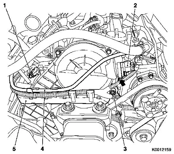
| 28. |
Remove wiring trough
| • |
Unclip wiring trough (5)
|
| • |
Disconnect 2 wiring harness plugs
| – |
Charge pressure sensor (1)
|
|
|
| 29. |
Remove camshaft sensor
|
|
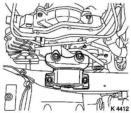
| 30. |
Remove right engine damping block
|
|
|
| 31. |
Detach right engine bracket (1)
| • |
Unscrew 3 bolts
Note: Lower bolt cannot
be removed
|
| • |
With right engine bracket adapter
|
|
|
|
| 32. |
Remove upper toothed belt cover
Important: Take care not to
damage the increment counter for the camshaft sprocket when
removing the upper toothed belt cover.
|
| • |
Unscrew 8 bolts
Note: Note dissimilar
bolt lengths
|
|
|
|
| 34. |
Remove torsional vibration damper (1)
|
|
|
| 35. |
Detach lower part of toothed belt cover
|
|
|
| 36. |
Remove right engine bracket
|
| 37. |
Set 1st cylinder to TDC
| • |
Install torsional vibration damper
|
| • |
Turn crankshaft evenly until TDC fixing bolts can be screwed
in
| – |
High pressure pump drive gear M8 (2)
Note: The mark on the
torsional vibration damper must align with the pin on the oil pump
cover (arrows)
|
|
| • |
Remove torsional vibration damper
|
|
|
|
| 38. |
Loosen toothed belt tension roller (1)
| • |
Loosen bolt of toothed belt tension roller (2)
|
| • |
Rotate toothed belt tension roller anticlockwise approx.
90°
|
| • |
Tighten bolt of toothed belt tension roller
|
|
| 39. |
Remove toothed belt
Note: Mark running
direction.
|
|
|
| 40. |
Detach oil pump drive gear (1)
| • |
Unscrew nut
Note: Counterhold with
socket wrench and loosen with wrench (2)
|
|
|
|
| 42. |
Remove toothed belt drive gear (1)
| • |
Remove bolt (3)
| – |
Counterhold using KM-662-C
|
|
| • |
Remove toothed belt drive gear
|
|
|
|
| 43. |
Remove oil pump (1)
| • |
Unscrew 9 bolts
Note: Note different
bolt lengths. Remove inner and outer rotor (2)
|
|
| 44. |
Clean sealing surfaces
| • |
Cylinder block, oil pump cover
|
|
|
|
| 46. |
Remove oil pump seal ring (2)
Important: Do not damage sealing
surfaces
|
| • |
Lever out seal ring
|
|
| 47. |
Remove front crankshaft front seal ring (1)
Important: Do not damage sealing
surfaces
|
| • |
Lever out seal ring
|
|
|
|
 Install
| 48. |
Install oil pump seal ring
| • |
Drive in seal ring with KM-657 until
flush
|
|
| 49. |
Install oil pump
| • |
Insert inner and outer rotor
|
| • |
Apply adhesive sealing compound
|
| • |
Attach oil pump cover (2)
|
|
|
|
| 50. |
Install front crankshaft seal ring
| • |
Drive in seal ring with KM-656 until
flush
|
|
|
|
| 51. |
Install toothed belt drive gear
| • |
Install sheet metal panel
|
| • |
Put toothed belt drive gear on
Note: Note woodruff
key
|
|
| 53. |
Install oil pump gear
Note: Pay attention to
installation position
| • |
Tighten nuts
Note: Counterhold with
socket wrench
|
|
| 54. |
Turn crankshaft
| • |
Install torsional vibration damper
|
| • |
Set crankshaft to 1st cylinder TDC
Note: Mark on torsional
vibration damper must align with pin on oil pump cover
| – |
Remove torsional vibration damper
|
|
|
| 56. |
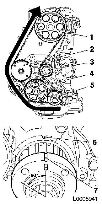
Install toothed belt
Note: TDC locking bolt
must be installed in the camshaft sprocket and marking (6) and (7)
must align.
| • |
Position toothed belt
| – |
Toothed belt must be tensioned in the direction of the arrow
from the toothed belt drive gear (5) via the oil pump drive gear
(4), via the high pressure pump drive gear (2) to the camshaft
sprocket (1)
|
|
| • |
Loosen toothed belt tension roller (3)
|
| • |
Remove TDC locking bolt
|
| • |
Rotate crankshaft 60° against direction of engine
rotation
|
| • |
Tighten toothed belt tension roller 38Nm
|
|
|
|
| 57. |
Timing, Check
| • |
Turn crankshaft 720° in the direction of rotation of the
engine
|
| • |
Mark on toothed belt drive gear (2) must align with cast lug
(1) on oil pump cover
|
| • |
Screw in TDC fixing bolts (arrows)
|
| • |
Install torsional vibration damper
| – |
Bolt in bolt
Note: The mark on the
torsional vibration damper (3) must align with the pin (4) on the
oil pump cover. If the TDC fixing bolts cannot be screwed in, basic
adjustment must be repeated
|
|
| • |
Unscrew TDC fixing bolts
|
| • |
Remove vibration damper
|
|
|
|
| 59. |
Attach right engine bracket
| • |
Insert lower bolt
| – |
Into right engine bracket and right engine bracket adapter
|
|
| • |
Fit right engine bracket with adapter
|
|
| 60. |
Attach lower part of toothed belt cover
|
| 62. |
Install upper toothed belt cover
| • |
Tighten 8 bolts 9.8 Nm
Note: Note dissimilar
bolt lengths
|
|
| 63. |
Fasten right engine bracket
| • |
Tighten 2 upper bolts 40 Nm
|
|
| 64. |
Install camshaft sensor
|
| 65. |
Attach wiring trough
| • |
Connect 2 wiring harness plugs
|
|
| 66. |
Install right engine damping block
| • |
On engine bracket
| – |
Tighten 2 bolts 60 Nm + 30° +
15°
|
|
|
| 68. |
Fasten right engine bracket
| • |
Tighten lower bolt 40 Nm
|
|
| 69. |
Attach coolant pump ribbed V-belt pulley
|
| 70. |
Install torsional vibration damper
| • |
Tighten 4 bolts 19.6 Nm
|
|
| 71. |
Install ribbed V-belt
Note: Observe running
direction and installation position
| • |
Release ribbed V-belt tensioner
|
|
| 72. |
Fasten coolant pump ribbed V-belt pulley
|
| 75. |
Clean sealing surfaces
| • |
Cylinder block, upper part of oil pan, lower part of oil
pan
|
|
| 76. |
Detach front reaction member
|
| 77. |
Attach oil pan upper part
| • |
Apply silicone sealing compound
|
Important: The application of
silicone sealing compound and installation of the lower part of the
oil pan, including torque test, must be completed within 10
minutes
|
| • |
Tighten 14 bolts 9.8 Nm
|
| • |
Tighten 4 M10 bolts 40 Nm
|
| • |
Attach intermediate shaft bearing support
|
| • |
Connect dynamic oil level check wiring harness plug
|
|
| 78. |
Attach front reaction member
|
| 79. |
Attach oil pan lower section
| • |
Apply silicone sealing compound
|
| • |
Tighten 15 bolts 9.8 Nm
|
|
| 80. |
Attach starter wiring harness
| • |
Electrically connect starter
|
| • |
Connect fuel pressure sensor wiring harness plug
|
|
| 81. |
Detach exhaust system
Note: Second person
required
| • |
Attach retaining rubber (5x)
|
|
| 82. |
Fasten front exhaust pipe
|
| 83. |
Install oil dipstick guide tube
|
| 84. |
Attach ribbed V-belt cover
|
| 86. |
Attach front right wheel
|
| 88. |
Fasten right front wheel
|
| 89. |
Install air cleaner housing
|
| 90. |
Install oil dipstick guide tube
|
| 91. |
Install oil filter element
| • |
Tighten oil filter housing cover 25
Nm
|
|
| 92. |
Top up engine oil
| • |
Start engine and allow to run until the oil check display
lights up
|
| • |
Check and correct engine oil level
|
| • |
Observe specified engine oil quantity
|
|
| 95. |
Program volatile memory
|
|
