|
Cylinder Head Gasket, Replace
Note: The customer
should be informed of the choice between ECOService and
ECOService-Flex before the oil change.
 Remove Remove
Important: On vehicles with ESP -
the steering angle sensor loses its basic adjustment each time the
battery is disconnected. It must be recalibrated.
|
| 2. |
Disconnect battery
|
| 3. |
Remove engine cover.
| • |
Detach engine cover
Note: Rubber retainers
must remain on the engine cover.
|
|
| 4. |
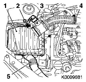
Remove air cleaner housing (1)
| • |
Disconnect wiring harness plug of mass air flow meter (3)
| – |
Unclip from retaining clip (arrow)
|
|
| • |
Detach front intake hose (5)
|
|
|
|
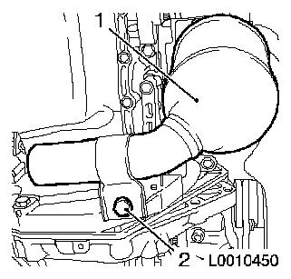
| 5. |
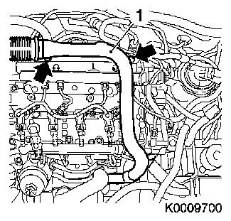
Remove charge air pipe (1)
| • |
Unscrew 2x bolt (arrows)
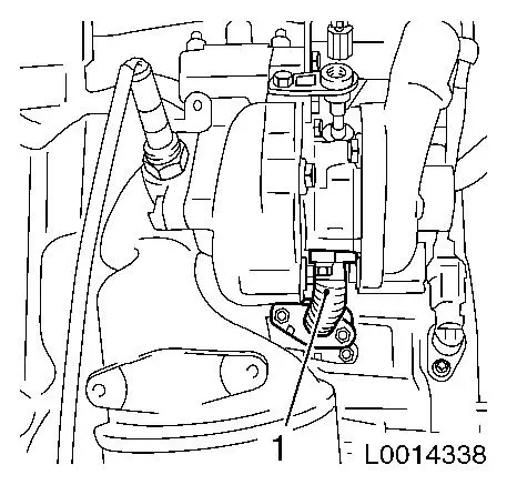
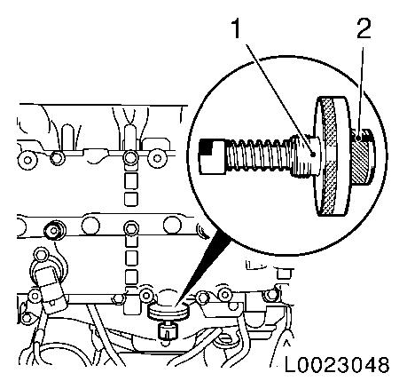
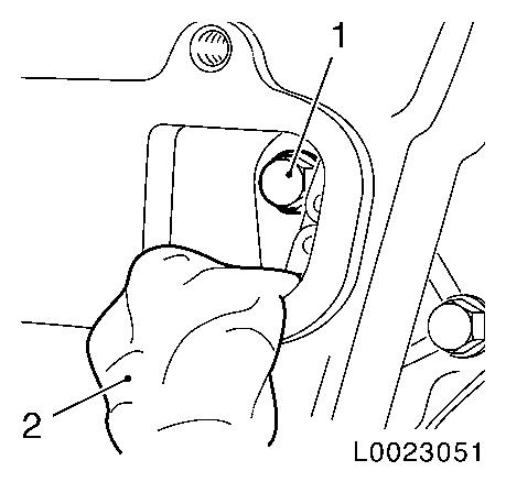
|
|
|
|
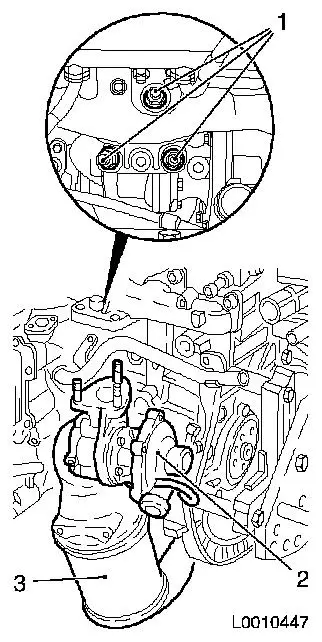
| 6. |
Separate wiring harness plug for differential pressure sensor
(1) and temperature sensor (3)
Note: On vehicles with
diesel particle filter
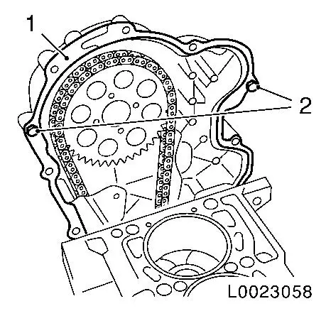
| • |
Unclip wiring harness from bracket (2)
|
|
|

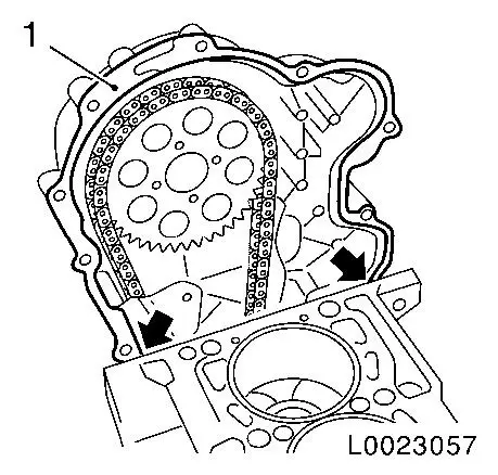
|
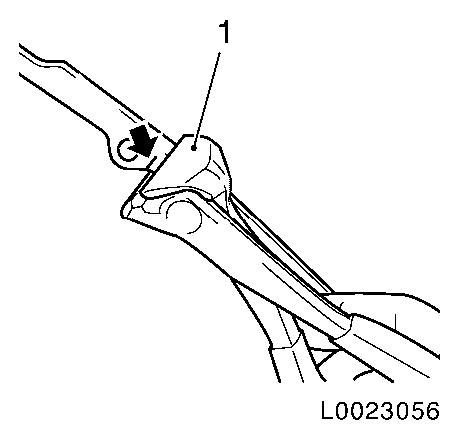
| 7. |
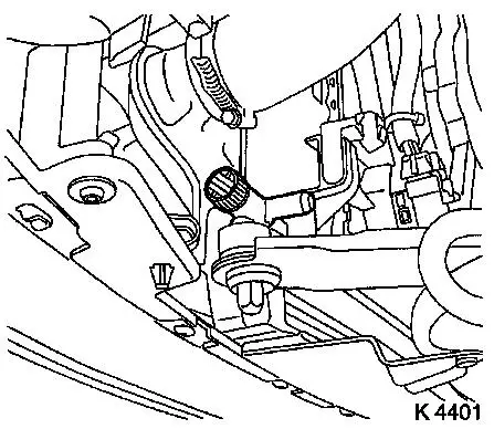
Drain coolant
| • |
Place collecting basin underneath.
|
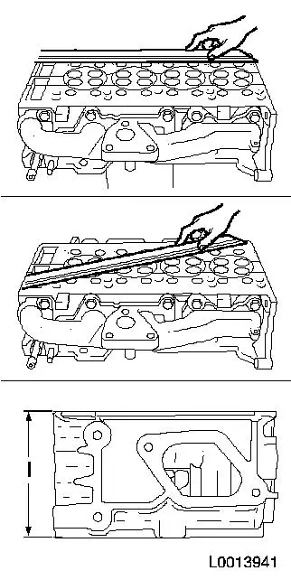
|
|
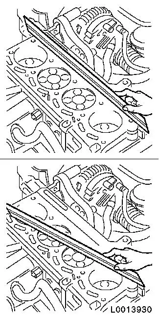
|
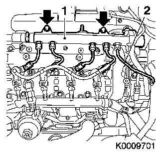
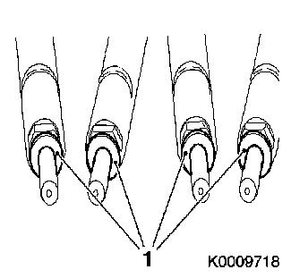
| 8. |
Remove wiring harness for engine management
| • |
Disconnect 4 glow plug wiring harness plugs
|
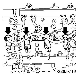
| • |
Disconnect 4 injector wiring harness plugs
|
| • |
Disconnect 7x wiring harness plugs
| – |
Fuel rail pressure sensor
|
| – |
Fuel rail pressure valve
|
|
| • |
Unclip wiring harness from bracket, oil filler pipe
|
| • |
Unclip wiring harness from bracket, coolant pipe
|
| • |
Disconnect wiring harness
|
| • |
Set wiring harness to one side
|
|
| 9. |
Disconnect coolant temperature sensor wiring harness plug
| • |
Unclip wiring harness from coolant pipe
|
|
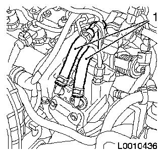
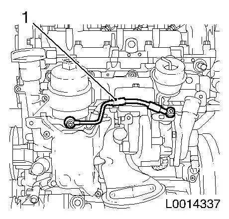
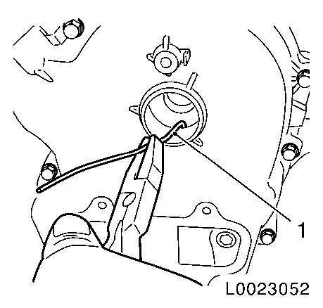
| 10. |
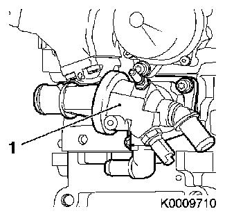
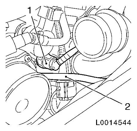
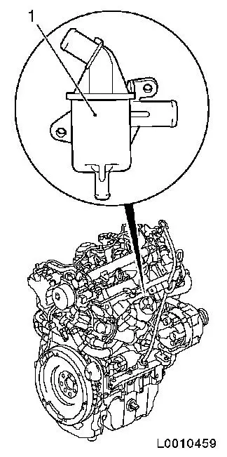
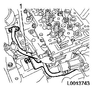
Detach coolant return hose from thermostat housing (1)
|
| 11. |
Detach upper coolant hose from thermostat housing
|
|
|
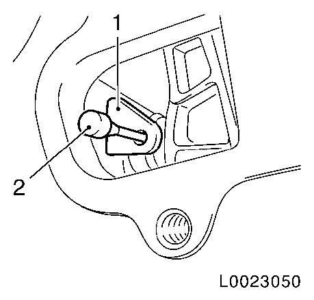
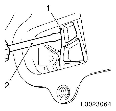
| 12. |
Detach brake servo vacuum line (1)
| • |
Disconnect quick-release coupling
|
|
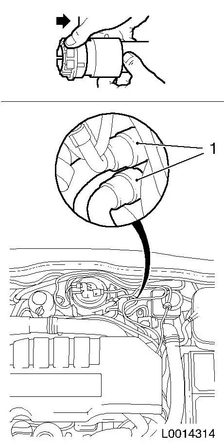
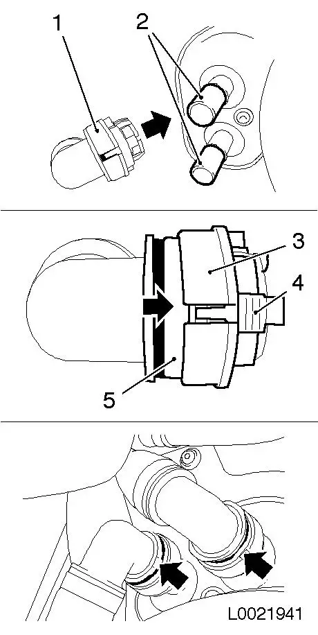
| 13. |
Separate vacuum line vacuum pump (2)
|
|
|
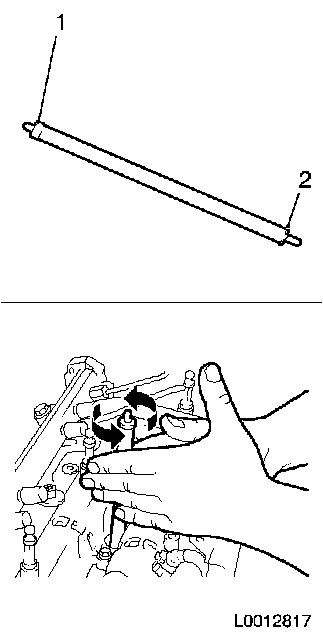
| 14. |
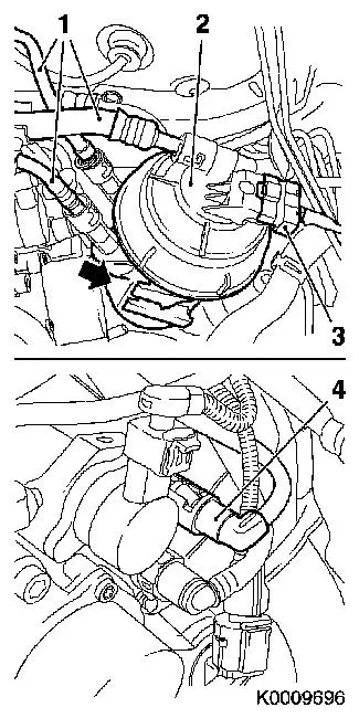
Remove fuel filter housing (2)
| • |
Disconnect 4 lines (1) and (4)
|
| • |
Disconnect 2 wiring harness plugs
|
| • |
Remove fuel filter housing and place in suitable container
|
|
|
|
| 15. |
Loosen coolant compensation tank
| • |
Unclip coolant compensation tank
|
|
| 16. |
Remove crash box
| • |
Unclip coolant line, expansion tank
|
| • |
Unscrew left nut on bulkhead
|
| • |
Loosen right nut on bulkhead
|
|
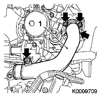
| 17. |
Remove charge air pipe at intake manifold (1)
| • |
Unscrew 4 bolts (arrows)
|
|
|
|
| 18. |
Detach 2x fuel line (1)
|
|
|
| 19. |
Detach high pressure line (2)
| • |
High-pressure line from high-pressure pump to fuel rail
|
|
| 20. |
Detach 4x high-pressure lines for injectors
|
| 21. |
Detach accumulator (1)
| • |
Unscrew 2x bolt (arrows)
|
|
|
|
| 22. |
Detach 4x oil leak line
| • |
Release 4x retaining clamp (arrows)
|
|
|
|
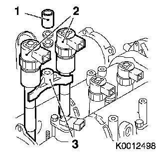
| 23. |
Release 2x injector bracket (3)
|
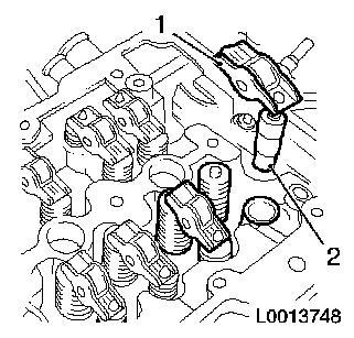
| 24. |
Remove 4 injectors
Note: The injectors (2)
can only be removed in pairs (cylinder 1+2 or cylinder 3+4).
|
|
|
| 25. |
Remove hose, timing case breather
|
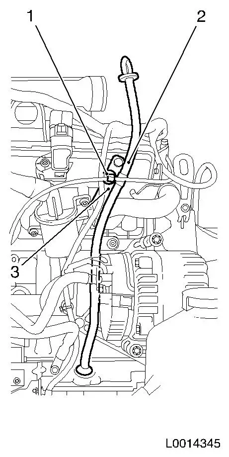
| 26. |
Detach oil dipstick guide tube (2)
| • |
Unclip wiring harness (3)
|
| • |
Unscrew threaded pins (1)
|
|
|
|
| 27. |
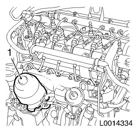
Detach oil separator (1) from cylinder block
|
|
|
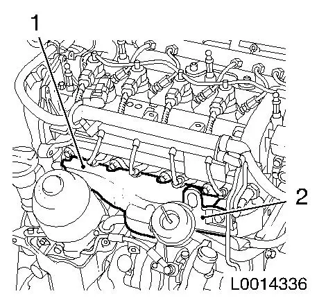
| 28. |
Separate 2x coolant hose (1) from heater core
| • |
Release 2x coolant hose in direction of arrow
|
|
|
|
| 29. |
Remove oil filter housing heat shield
|
|
|
| 30. |
Remove heat shield exhaust manifold (1)
| • |
Remove bolt
| – |
Remove engine transport shackle (2)
|
|
|
|
|
| 31. |
Remove turbocharger oil return line (1)
|
|
|
| 32. |
Detach catalytic converter (1) from transmission
| • |
Detach catalytic converter bracket
|
|
|
|
| 33. |
Remove turbocharger oil feed line (1)
|
|
|
| 34. |
Detach turbocharger (2) with catalytic converter (3) from
exhaust manifold
| • |
Unscrew 3x nut (1)
Note: Carefully lower
turbocharger. Turbocharger is not removed completely.
|
|
|
|
| 35. |
Remove coolant pipe (1) from heat exchanger
| • |
Unscrew 2x bolts on heat exchanger
|
| • |
Unscrew bracket on cylinder head
|
|
| 36. |
Detach coolant pipe from cylinder head on gearbox side
| • |
Unscrew bolt, bracket, coolant pipe
|
|
|
|
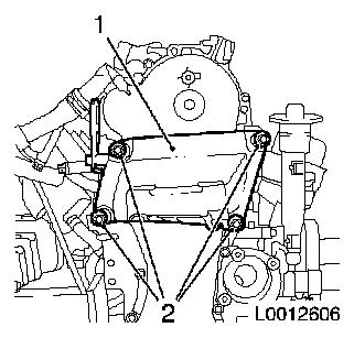
| 37. |
Remove right engine damping block 
|
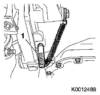
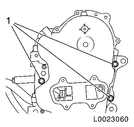
| 38. |
Remove support for engine damping block (1) from cylinder head
and cylinder block
|
|
|
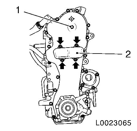
| 39. |
Unscrew closure bolt (1)
|
| 40. |
Remove closure cap (2)
| • |
Unscrew 4 bolts (arrows)
|
|
|
|
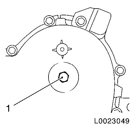
| 41. |
Remove exhaust camshaft closure bolt from camshaft housing
| • |
Clean 2x threads on closure bolt and camshaft housing
|
|
|
|
| 42. |
Lock exhaust camshaft
| • |
Screw reference drift EN-46781 (1)
into exhaust camshaft
Note: Check for proper
installation position!
|
| • |
The reference drift used for fixing must be fitted in a
horizontal position.
Note: As an aid, apply
marking (2) to reference drift.
|
| • |
Turn exhaust camshaft until reference drift fixing visibly
engages
Note: Using a suitable
tool through the opening in the timing case, turn the screw on
camshaft drive gear for exhaust camshaft.
Note: The reference
drift is securely engaged in the camshaft when it can no longer be
turned.
|
|
|
|
| 43. |
Raise vehicle all the way
|
| 44. |
Lock the crankshaft
| • |
Insert EN-46785 (1) through the
opening in the bottom of the gearbox bell housing
|
| • |
To fix EN-46785 , attach screw (2) to
gearbox bolt screw head.
|
| • |
Carefully turn crankshaft until EN-46785 engages in flywheel
|
|
|
|
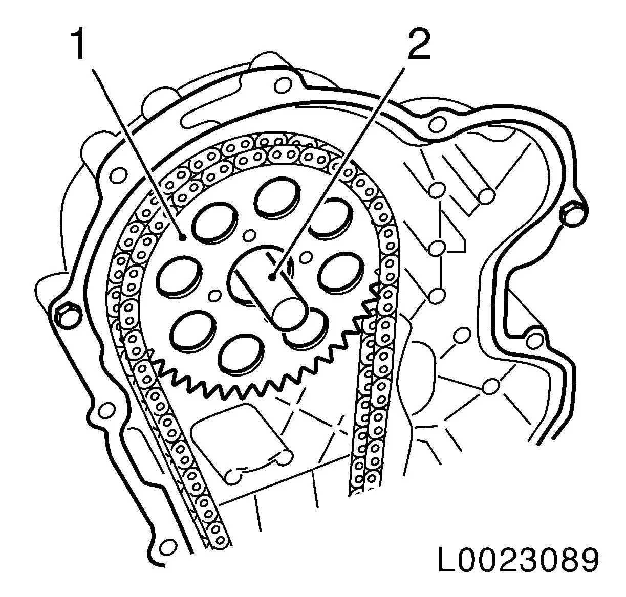
| 46. |
Detach drive gear for exhaust camshaft
| • |
Detach drive gear screw (1) with suitable tool through the
opening in the timing case.
Note: Do not unscrew
bolt.
|
|
|
|
| 47. |
Tighten timing chain tensioner
| • |
Tighten timing chain tensioner (1) with a suitable tool and
lock in pretensioned position with KM-955-1 (2).
|
|
|
|
| 48. |
Detach sliding rail, timing chain, from cylinder head
| • |
Remove bolt (1)
Note: With a clean
cloth (2), prevent bolt from dropping into timing case.
|
|
|
|
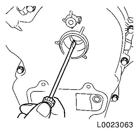
| 49. |
Detach exhaust camshaft drive gear from exhaust camshaft
| • |
Remove drive gear from exhaust camshaft with a rigid angled
wire (1).
|
|
|
|
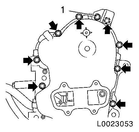
| 50. |
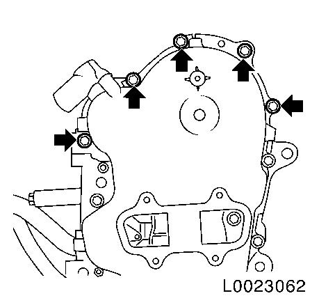
Detach timing case from camshaft housing
| • |
Unscrew bolt, bracket (1)
|
| • |
Unscrew 8 bolts (arrows)
|
|
|
|
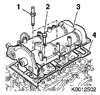
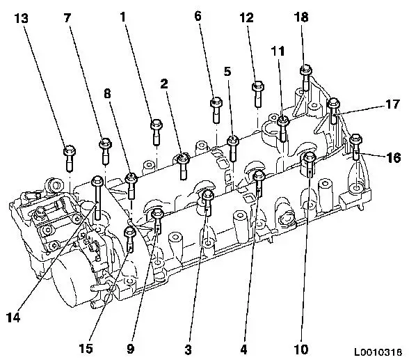
| 51. |
Remove camshaft housing (3)
| • |
Unscrew 16x bolt (2)
Note: Note dissimilar
bolt lengths
|
| • |
Unscrew 2x threaded pin (1)
|
| • |
Carefully detach camshaft housing from timing case using a
rubber mallet
|
| • |
Carefully detach gasket between camshaft housing and timing
case from the camshaft housing using a plastic spatula
|
| • |
Remove camshaft housing
|
|
|
|
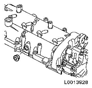
| 52. |
Remove 16 roller cam followers (1) with valve play adjusters
(2)
Note: Put down in
removal order.
|
|
|
| 53. |
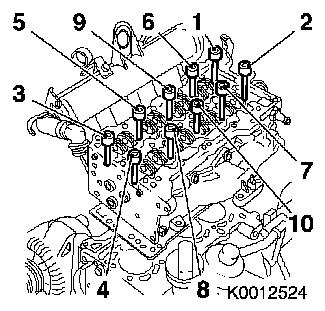
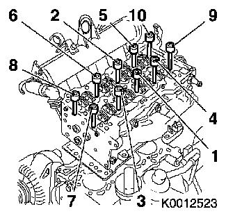
Remove cylinder head
| • |
Detach 10x bolts in sequence shown
|
| • |
Carefully detach cylinder head from timing case using a rubber
mallet
|
| • |
Carefully detach gasket between cylinder head and timing case
from the cylinder head using a plastic spatula
|
| • |
Remove cylinder head gasket
|
|
|
|
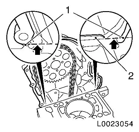
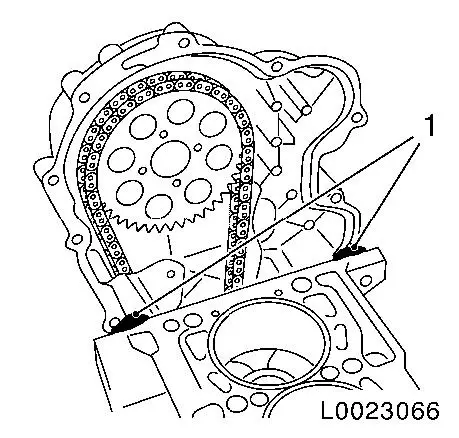
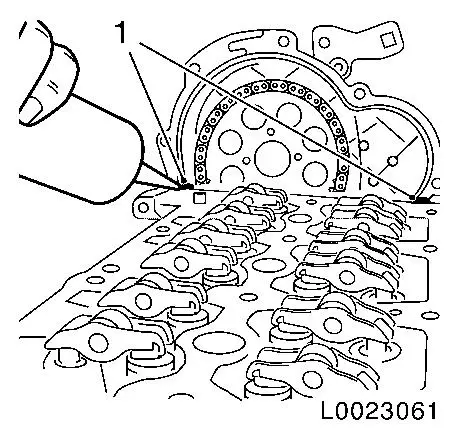
| 54. |
Remove timing case gasket
Note: Sealing lip (2)
must not be damaged
| • |
Cut the elastomer sealing lip (arrow) flush to the cylinder
head using a sharp knife
|
| • |
Detach gasket from timing case with a plastic spatula and
carefully fold up at the nominal break point (1).
|
| • |
Remove gasket residue and thoroughly clean all sealing
surfaces
Note: Ensure that no
gasket residue remains at the joining points between the timing
case and cylinder block, and that no gasket residue drops into the
timing case.
|
|
|
|
 Install
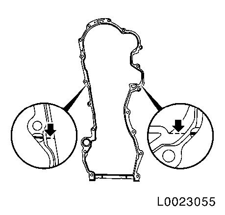
| 55. |
Cut elastomer sealing lip (arrow) at nominal break point of new
gasket using a sharp knife.
|
|
|
| 56. |
Separate new timing case gasket at lower nominal break
point
| • |
Separate gasket at both nominal break points (arrow) with
pincers (1)
Note: The cutting tool
must have a straight cutting surface.
|
|
|
|
Important: The new upper gasket
and old lower gasket must not overlap!
|
| 57. |
Adapt new seal on timing case
| • |
Adapt the new gasket (1) to the contact surface of cylinder
block to timing case using pincers until the gasket lies flush on
the cylinder block and timing case (arrow), and the holes in the
gasket and timing case align
|
|
|
|
| 58. |
Clean all contact surfaces
|
| 59. |
Check cylinder head for plane surface
| • |
Use straight edge and feeler gauge to check length and breadth
of cylinder head sealing surfaces for torsion
|
| • |
Maximum deflection is 0,10 mm
|
|
| 60. |
Measure the height of the cylinder head
| • |
Sealing surface to sealing surface
|
| • |
Dimension l: = 105.45 –105.55
mm
|
|
|
|
| 61. |
Check cylinder head for plane surface
| • |
Use straight edge and feeler gauge to check length and breadth
of cylinder block sealing surfaces for torsion
|
|
|
|
| 62. |
Raise vehicle all the way
|
| 63. |
Remove crankshaft lock EN-46785
|
| 65. |
Set piston of cylinder 1 to TDC
| • |
Tighten timing chain
Note: Timing chain must
be tensioned to prevent the chain slipping when the crankshaft is
turned.
| – |
Using a suitable tool (2), press camshaft drive gear (1) up and
fix
Note: 2nd person
required
|
|
| • |
Turn crankshaft in direction of engine rotation at torsional
vibration damper
|
| • |
Release timing chain
Note: Carefully lay
camshaft drive pinion on web on timing case
|
|
|
|
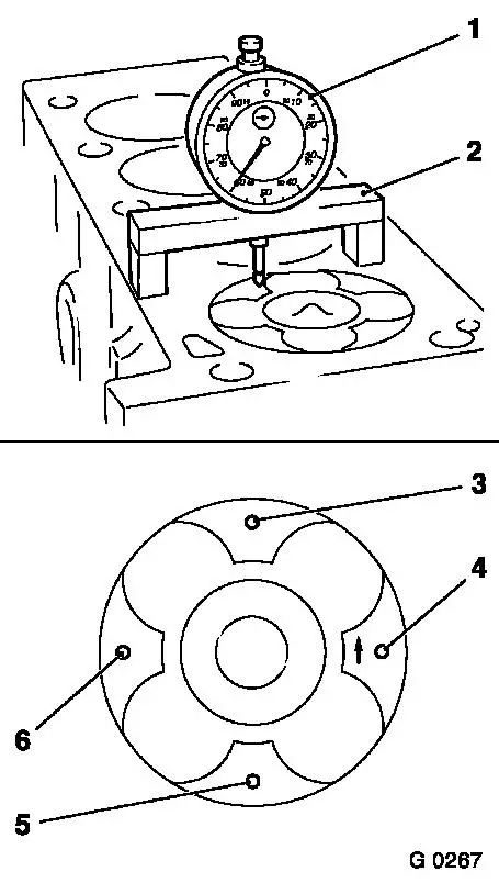
| 66. |
Measure piston projection
| • |
Place probe of MKM-571-B in position
on cylinder block
|
| • |
Set dial to zero
| – |
Determine high point by turning crankshaft
|
|
| • |
Measure piston projection
| – |
Measure on all 4 pistons
|
| – |
Carry out measurement on two different locations (3 and 4) or
(5 and 6)
|
|
|
|
|
| 67. |
Raise vehicle all the way
|
| 68. |
Insert crankshaft lock EN-46785
|
Important: The largest determined
piston projection determines the selection of the cylinder head
gasket with appropriate identification.
|
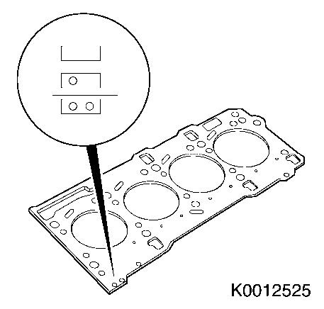
| 70. |
Replace cylinder head gasket
|
Piston projection
|
Thickness of cylinder head gasket
|
Code
|
|
0.028 - 0.127 mm
|
0.67 - 0.77 mm
|
no hole
|
|
0.128 - 0.227 mm
|
0.77 - 0.87 mm
|
one hole
|
|
0.228 - 0.327 mm
|
0.87 - 0.97 mm
|
two holes
|
|
|
|
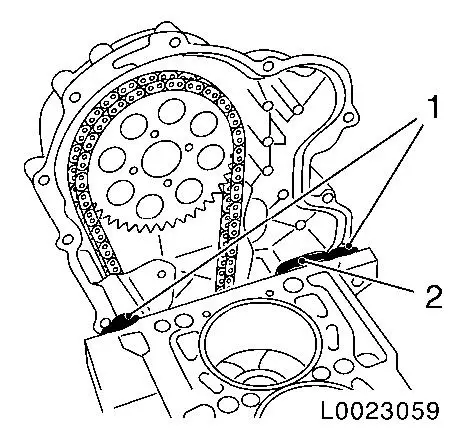
| 71. |
Apply sealant
Important: If the sealing tab (2)
is damaged, remove with a suitable cutting tool and apply sealant
to the timing case contact surface!
|
| • |
Apply sealant to the contact surface of cylinder block to
timing case (1)
|
|
|
|
| 72. |
Attach timing case gasket
Note: Proceed to fit
cylinder head gasket within 10 minutes due to sealant reaction
time
| • |
Place new gasket (1) on timing case
|
| • |
For fixing, insert 2x bolts M6 (2) in timing case bores and
tighten 2x nuts M6 hand-tight
Note: Bolts must be
inserted in bores shown above cylinder head
|
|
|
|
| 73. |
Attach new cylinder head gasket
| • |
Apply sealant to cylinder block
| – |
At contact surfaces cylinder block to timing case (1)
|
|
| • |
Apply cylinder head gasket
Note: Note guide
bushings.
|
| • |
Apply sealant to cylinder head gasket
| – |
At contact surfaces cylinder head gasket to timing case (1)
|
|
|
|
|
| 74. |
Apply cylinder head
| • |
Place cylinder head on guide sleeves
Note: 2nd person
required.
|
| • |
Screw in 10 new bolts
Note: Do not tighten
bolts yet
|
|
| 75. |
Attach timing case to cylinder head
| • |
Align cylinder head carefully to timing case using a rubber
mallet
|
| • |
Screw in 3x bolts (1) until cylinder head lies against timing
case
|
|
|
|
| 76. |
Attach cylinder head to cylinder block
| • |
Tighten 10x bolts in sequence shown 40
Nm + 90°+ 90°
|
|
|
|
| 77. |
Insert 16 roller cam followers with valve play adjusters
Note: Observe removal
sequence. Before installation, place roller cam followers and
hydraulic valve lifters in engine oil.
|
| 78. |
Remove oil and grease from contact surfaces of exhaust
camshaft, drive gear, bolts and threads in exhaust camshaft
|
| 79. |
Attach new camshaft housing gasket
| • |
Clean all contact surfaces
|
| • |
Apply sealant to the contact surface of cylinder head to timing
case (1)
|
| • |
Apply camshaft housing gasket
Note: Check 2x centring
pins
|
| • |
Apply sealant to contact surface of gasket, camshaft housing to
timing case (1)
|
|
|
|
| 80. |
Install camshaft housing
| • |
Unscrew 2x screw connection on timing case gasket
|
| • |
Tighten 16x bolts in tightening sequence until camshaft housing
lies flat on the cylinder head
Note: Do not tighten
bolts yet
Note: Note longer bolt
(14)
|
|
|
|
| 81. |
Attach timing case to camshaft housing
| • |
Carefully align camshaft housing to timing case using a rubber
mallet
|
| • |
Screw in 5x bolts (arrows) until camshaft housing lies on
timing case
|
|
|
|
| 82. |
Attach camshaft housing
| • |
Tighten 16x bolts M7 according to tightening sequence 18 Nm
|
| • |
Tighten 2 stud bolts (M8) 25 Nm
|
|
|
|
| 83. |
Attach timing case
| • |
Tighten 8x bolts (arrows) 9 Nm
|
| • |
Screw in bolt (1) bracket, and tighten 9 Nm
|
|
Important: Contact surfaces of
exhaust camshaft, drive gear, bolts and threads in exhaust camshaft
must be free from oil and grease!
|
| 84. |
Insert drive gear for exhaust camshaft
| • |
Lay drive gear on exhaust camshaft with suitable tool
|
| • |
Bolt in bolt
Note: Do not tighten
yet
|
|
|
|
| 85. |
Attach sliding rail, timing chain, to cylinder head
|
| 86. |
Tension timing chain tensioner
| • |
Release timing chain tensioner with suitable tool and remove
KM-955-1
|
|
| 87. |
Attach drive gear for exhaust camshaft
| • |
Tighten bolt 150 Nm
Note: During tightening
of the timing chain, a second person must tension the timing chain
tensioner (1) with a suitable tool (2).
|
|
|
|
| 88. |
Remove exhaust camshaft lock
| • |
Remove camshaft reference drift EN-46781
|
|
| 89. |
Raise vehicle all the way
|
| 90. |
Remove crankshaft lock
|
| 91. |
Timing, Check
| • |
Turn crankshaft in direction of engine rotation at torsional
vibration damper flange bolt by approx. 700° (2 revolutions)
|
| • |
Fit camshaft reference drift EN-46781
(1) in camshaft housing for exhaust camshaft
|
| • |
Check for proper installation position
Note: The fixing
reference drift must be fitted in a horizontal position. Fit the
guide mark on the reference drift (arrow).
|
| • |
Turn crankshaft in direction of engine rotation until EN-46781 engages in exhaust camshaft
|
| • |
Raise vehicle all the way
|
| • |
Turn crankshaft until EN-46785
engages in flywheel
|
| • |
If EN-46785 does not engage in the
flywheel, repeat the "Timing adjustment" procedure
|
|
| 95. |
Fit exhaust camshaft closure bolt
| • |
Coat closure bolt with thread locking compound
|
| • |
Tighten closure bolt 15 Nm
Note: Complete working
step within 10 minutes because of the reaction time of the thread
locking compound.
|
|
| 96. |
Fit timing case closure cap
| • |
Check gasket for damage
|
|
| 97. |
Install timing case closure bolt
| • |
Check gasket for damage
|
|
| 98. |
Attach support for engine damping block to cylinder head and
cylinder block
| • |
Insert and tighten 4x bolts 60
Nm
|
|
| 99. |
Install right engine damping block
|
| 100. |
Attach coolant pipe to cylinder head on gearbox side
| • |
Tighten bolt bracket, coolant pipe 9
Nm
|
|
| 101. |
Install coolant pipe between heat exchanger and thermostat
housing
| • |
Tighten bolts, bracket to cylinder head 9 Nm
|
| • |
Tighten 2x bolts on heat exchanger 9
Nm
|
|
| 102. |
Attach turbocharger to exhaust manifold
| • |
Replace gasket, oil return line, turbocharger
|
| • |
Tighten 3 new nuts 25 Nm
|
|
| 103. |
Attach turbocharger oil return line at cylinder block
| • |
Tighten 2 bolts, oil return line 9
Nm
|
|
| 104. |
Attach bracket, catalytic converter to transmission
|
| 105. |
Install turbocharger oil feed line
| • |
Tighten 2 banjo bolts 12 Nm
|
|
| 106. |
Attach heat shield to exhaust manifold
| • |
Insert engine transport shackle
|
| • |
Screw in bolt and tighten 25 Nm
|
|
| 107. |
Attach heat shield to oil filter housing
|
| 108. |
Attach oil separator to cylinder block
| • |
Insert and tighten 2x bolts 9 Nm
|
|
| 109. |
Attach oil dipstick guide tube to bracket
|
| 110. |
Attach bracket, differential pressure sensor for diesel
particle filter
Note: On vehicles with
diesel particle filter
| • |
Install body-bound rivet
|
|
| 111. |
Attach hose, timing case breather
|
Important: The following
installation sequence must be observed
|
| 112. |
Attach coolant hose to heater core
| • |
Push on 2x quick-release fitting (1) to stop on connection port
for heater core (2)
Note: Note colour
marking applied
|
| • |
Push 2x lock (3) for quick-release fittings to stop in
direction of arrow at the same time as pressing the release button
(4)
| – |
Colour rings (5) must be visible
|
|
| • |
Check correct seat of quick-release fittings and visibility of
colour rings (5)
|
|
|
|
| 113. |
Clean 4 injector seats with EN-47632
| • |
Loosen dirt with brush side (1)
|
| • |
Remove dirt with sponge side (2)
|
|
|
|
| 114. |
Replace 4x seal ring
| • |
For injectors in camshaft housing
|
|
| 115. |
Install 4 injectors
Note: Injectors can
only be inserted in pairs (cylinder 1+2 or cylinder 3+4).
| • |
Replace 4 injector seal rings (1)
|
|
|
|
| 116. |
Fasten 2 injector brackets
|
| 117. |
Attach 4x oil leak line
| • |
Lock 4x retaining clamp
|
|
| 119. |
Attach high pressure line for high pressure pump to fuel
rail
| • |
Tighten union nut (M14) 28 Nm
|
| • |
Tighten union nut (M12) 24 Nm
|
|
| 121. |
Attach 4 high-pressure lines
| • |
Tighten 4 union nuts (M14) 28 Nm
|
| • |
Tighten 4 union nuts (M12) 24 Nm
|
|
| 123. |
Install fuel filter housing
| • |
Connect 2 wiring harness plugs
|
|
| 124. |
Attach vacuum line to control unit charge pressure
|
| 125. |
Attach vacuum lines to vacuum pump
| • |
Close quick-release fitting
|
|
| 126. |
Connect coolant temperature sensor wiring harness plug,
thermostat housing
|
| 127. |
Attach upper coolant hose to thermostat housing
|
| 128. |
Connect coolant return hose to thermostat housing
|
| 129. |
Attach wiring harness for engine management
| • |
Connect 7 wiring harness plugs
|
|
| 130. |
Connect wiring harness plug for differential pressure sensor
and temperature sensor
Note: On vehicles with
diesel particle filter
| • |
Clip wiring harness to bracket
|
|
| 131. |
Attach coolant pipe to cylinder block
| • |
Tighten bolt of bracket, coolant pipe
|
|
| 132. |
Fit charge air pipe to intake manifold
|
| 133. |
Fit charge air pipe at turbocharger
| • |
Close quick-release fitting
|
|
| 134. |
Fasten coolant compensation tank
| • |
Clip in coolant compensation tank
|
|
| 135. |
Install charge air pipe
|
| 136. |
Install air cleaner housing
| • |
Attach front intake hose
|
| • |
Connect wiring harness plug of mass air flow meter
|
|
| 137. |
Install engine cover.
|
| 139. |
Top up and bleed cooling system
|
| 140. |
Program volatile memory
|
|
