|
Repair engine using a short block (Z 12 XE, Z 12
XEP, Z 14 XEP, with air conditioning)
 Remove Remove
| 1. |
Remove engine - see operation "J 340100 Removing and installing
engine"
|
| 2. |
Detach manual transmission from engine - see operation "J340100
007 Manual transmission to engine, remove and install"
|
| 3. |
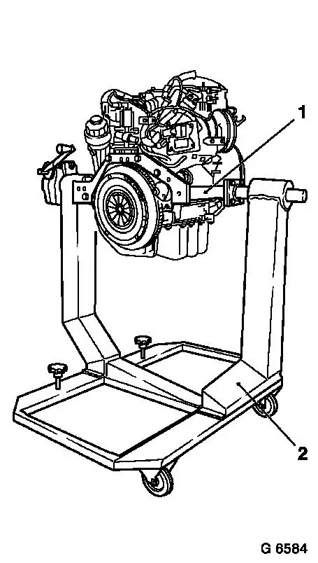
Install engine
| • |
Attach KM-412-18 (1) to engine
|
| • |
Install engine in KM-412 (2)
|
| • |
Tighten 8 bolted connections
|
|
|
|
| 4. |
Drain engine oil
| • |
Place collecting basin underneath.
|
| • |
Remove oil filter housing cover
|
| • |
Remove oil filter element
|
|
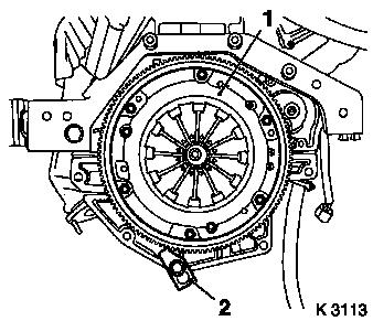
| 5. |
Remove clutch - see operation "Remove and install thrust plate
and clutch disk" in group "K"
|
|
|
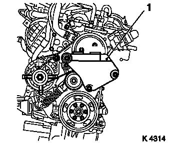
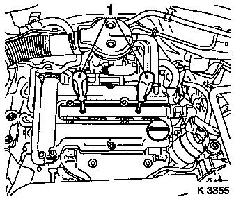
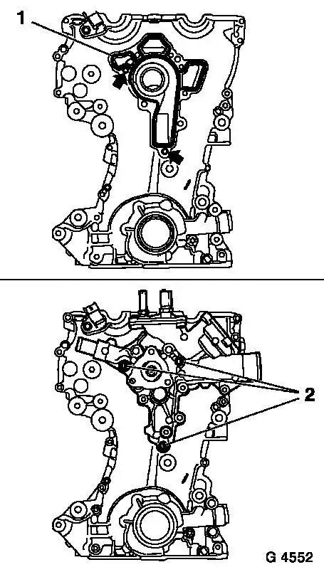
| 7. |
Detach right engine bracket (1)
|
| 8. |
Install oil drain bolt
| • |
Remove collecting basin
|
|
|
|
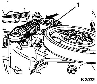
| 9. |
Remove ribbed V-belt
Note: Mark running
direction.
| • |
Tension ribbed V-belt tensioner in direction of arrow
|
|
| 10. |
Detach coolant pump ribbed V-belt pulley
|
| 11. |
Detach crankshaft ribbed V-belt pulley
| • |
Counterhold at crankshaft hub bolt
|
|
|
|
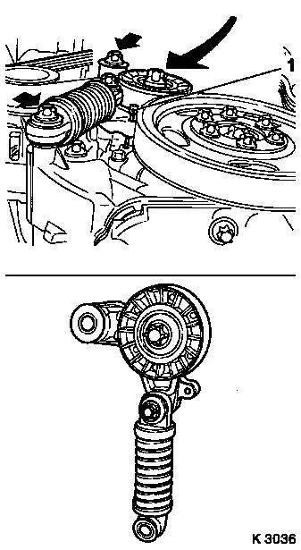
| 12. |
Detach ribbed V-belt tensioner
Note: Ensure that the
ribbed V-belt tensioner is stored in a proper manner (arrow
pointing upwards). If this is not guaranteed, the ribbed V-belt
tensioner must be bled. At least five strokes must be performed
(tensile/pressure load), whereby the load speed should be constant
and the application of load even. Damage to the tension element
must be avoided!
| • |
Tension ribbed V-belt tensioner in direction of arrow
|
| • |
Release ribbed V-belt tensioner
|
| • |
Unscrew 2 bolts (arrows)
|
|
|
|
| 13. |
Disconnect engine wiring harness
| • |
Detach alternator wiring harness
|
| • |
Detach starter wiring harness
|
|
|
|
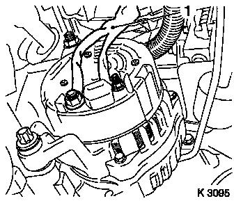
| 14. |
Detach alternator
| • |
Undo 2 screw connections
|
|
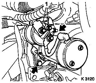
| 15. |
Remove starter
| • |
Unscrew 2 bolts (arrows)
|
|
|
|
|
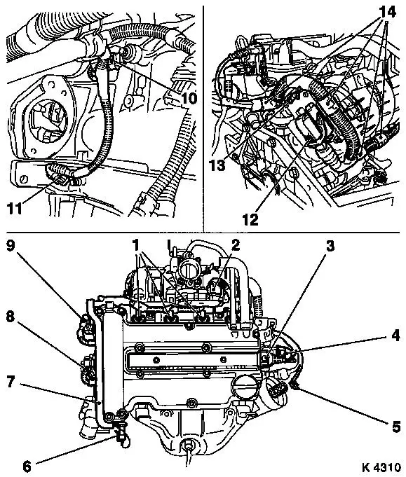
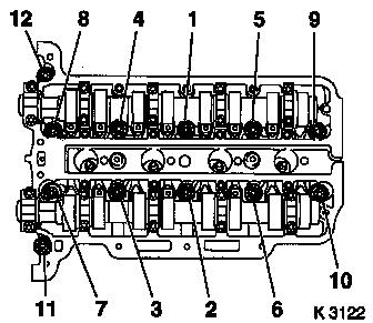
| 16. |
Remove wiring harness for engine management
| • |
For Z 12 XEP, Z 14 XEP: remove fuel rail cover
|
| • |
Disconnect 12 engine management wiring harnesses
| – |
Oil pressure switch (6), coolant temperature sensor (8),
camshaft sensor (9), throttle valve module (2), engine control unit
(12), exhaust gas recirculation valve (4), ignition module (3),
knock sensor (10), crankshaft sensor (11), injectors (1)
|
|
| • |
Unbolt ground cable for engine control unit (13).
|
| • |
Unclip wiring trough (7)
|
|
| 17. |
Detach 2 coolant hoses from coolant pump
|
|
| 18. |
Detach coolant hose from exhaust gas recirculation valve
coolant flange
|
| 19. |
Remove oil dipstick guide tube
|
| 20. |
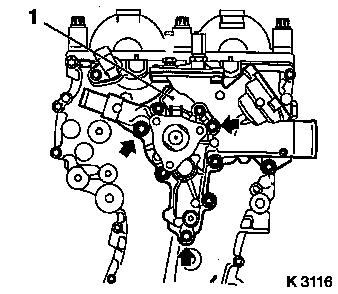
Detach coolant pump (1)
Note: Note guide
bushings during removal
| • |
Place collecting basin underneath.
|
| • |
Unscrew 9 bolts
Note: Pay attention to
different bolt lengths (arrows = short bolts)
|
|
|
|
| 21. |
Remove exhaust manifold heat shield
|
| 22. |
Remove exhaust manifold
|
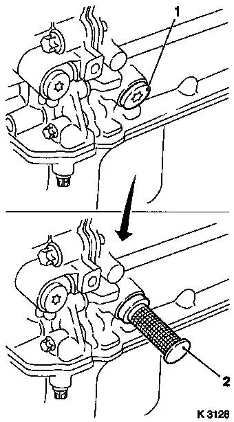
| 23. |
Remove ignition module
| • |
Remove ignition module cover
|
| • |
Extract using KM-6009 (1)
Note: Do not tilt
|
|
| 24. |
Detach cylinder head cover
| • |
Detach engine vent hose
|
|
|
|
| 25. |
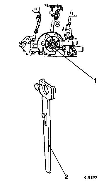
Loosen crankshaft hub bolt (1)
Note: Second person
required
| • |
Attach KM-956-1 KM-956-2 (2)
|
| • |
Counterhold KM-956-1 KM-956-2
|
|
|
|
|
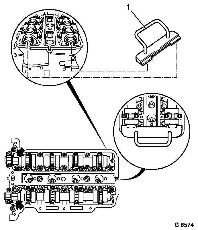
| 26. |
Adjust camshafts
| • |
Uniformly rotate crankshaft in direction of engine rotation
with KM-956-1 KM-956-2 until KM-953 (1)
engages in camshaft groove as far as it will go
|
|
| 27. |
Remove crankshaft hub
Note: Pay attention to
installation position
| • |
Remove with KM-956-1 KM-956-2
|
|
|
|
| 29. |
Remove timing case
| • |
Unscrew 15x bolt (arrows)
| – |
Pay attention to bolt lengths
|
| – |
Do not damage camshaft sensor (1).
|
|
| • |
Lever out timing case seal ring
Note: Do not damage
sealing surface
|
|
|
|
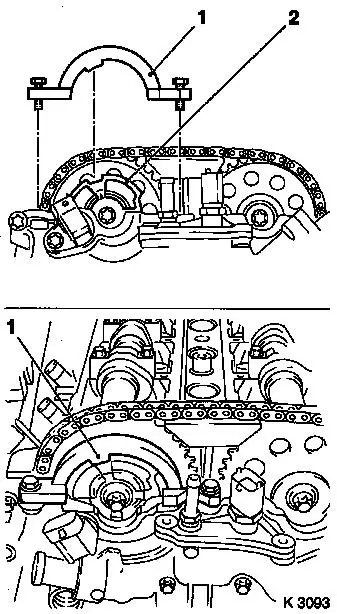
| 30. |
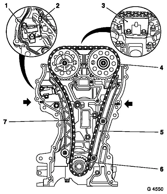
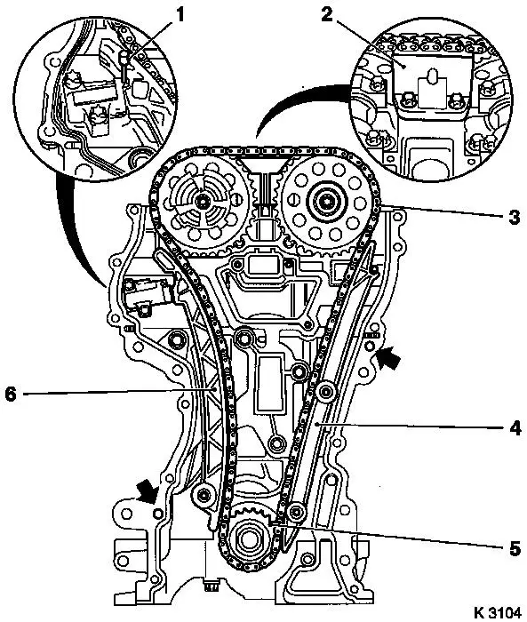
Remove chain drive
| • |
Loosen camshaft sprocket bolts
| – |
Counterhold camshafts at hexagonal section
|
|
| • |
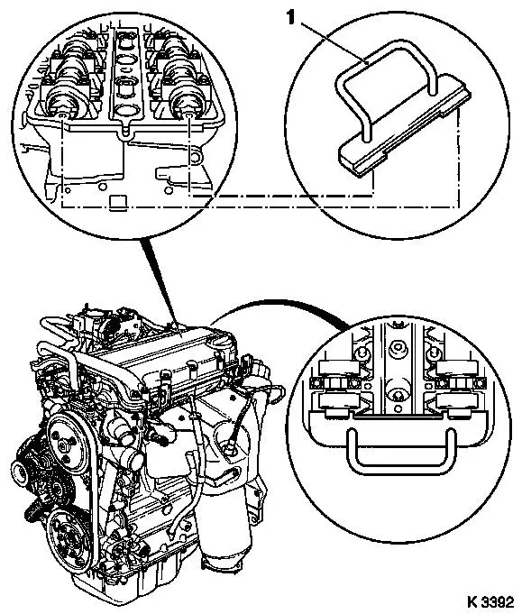
Lock chain tensioner (1)
|
| • |
Detach sliding rail (3), guide rail (5), tension rail (7) and
camshaft sprockets
|
| • |
Remove timing chain (4) with drive sprocket (6)
|
| • |
Remove timing case gasket.
|
|
|
| 31. |
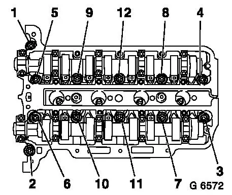
Remove cylinder head
| • |
Unscrew 12 bolts
Note: Undo cylinder
head bolts in depicted order
| – |
Loosen cylinder head bolts (90°)
|
| – |
Loosen cylinder head bolts (180°)
|
| – |
Remove cylinder head bolts
|
|
| • |
Place cylinder head on wooden blocks
|
| • |
Remove cylinder head gasket
|
|
|
|
| 32. |
Remove oil filter housing
|
| 34. |
If present: detach oil baffle plate
|
| 35. |
Remove crankshaft sensor
|
| 36. |
Remove cylinder block
| • |
Suspend engine on workshop crane
|
|
 Install
| 37. |
Install cylinder block
| • |
Attach KM-412-18 to engine
|
|
| 39. |
Drive 6 guide sleeves into cylinder block with KM-427
|
| 40. |
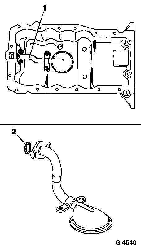
Remove oil intake pipe (1)
|
| 41. |
Clean sealing surfaces
| • |
Cylinder block, cylinder head, cylinder head cover, oil filter
housing, crankshaft bearing bridge, timing case, oil pan, coolant
pump, exhaust manifold
|
|
|
|
| 42. |
Inspect components
Note: If cylinder head
is to be checked and overhauled : Remove all outer attaching parts
from cylinder head.
| • |
Cylinder block, cylinder head, cylinder head cover, oil filter
housing, crankshaft bearing bridge, chain drive, timing case, oil
pan, coolant pump, exhaust manifold
|
|
| 43. |
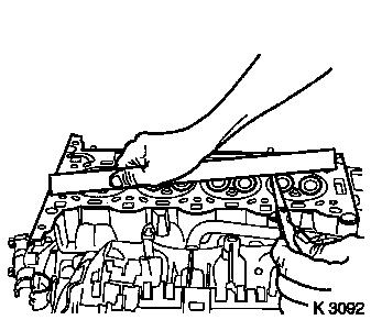
Check that cylinder head has plane surface
| • |
With straightedge, feeler gauge
|
|
|
|
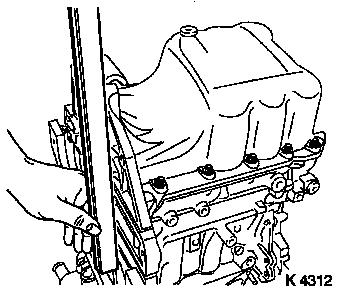
| 44. |
Lock crankshaft
| • |
Remove closure bolt (1)
|
| • |
Insert KM-952 (2)
| – |
Turn crankshaft uniformly until KM-952 engages
|
|
|
|
|
| 45. |
Attach oil baffle plate
|
| 46. |
Install oil filter housing
| • |
Replace oil filter element
|
| • |
Attach oil filter housing cover
|
|
|
| 47. |
Adjust camshafts
| • |
Insert KM-953
| – |
Turn the camshafts at hexagonal section
|
|
|
|
| 48. |
Install cylinder head
| • |
Replace gasket
Note: TOP/OBEN mark
must be on top
|
| • |
Replace cylinder head bolts
|
| • |
Align cylinder head to cylinder block using straightedge
|
| • |
Tighten 12 bolts 25 Nm + 60° +
60° + 60°
Note: Note tightening
sequence.
|
|
|
|
|
| 49. |
Attach timing chain
| • |
Replace timing case gasket
Note: Pay attention to
correct seating (arrows)
|
| • |
Attach exhaust camshaft sprocket
|
| • |
Install timing chain (3)
|
| • |
Insert intake camshaft sprocket with phase sensor disc in
timing chain
| – |
Bolt in bolt
Note: It must be
possible to rotate phase sensor disk by hand
|
|
|
|
|
| 50. |
Attach timing chain tension rail (6)
| • |
Tighten bolt 20 Nm
Note: Ensure that
timing chain is correctly seated
|
|
| 51. |
Attach timing chain guide rail (4)
| • |
Tighten 2 bolts 8 Nm
Note: Ensure that
timing chain is correctly seated
|
|
| 52. |
Attach timing chain sliding rail (2)
|
| 53. |
Release chain tensioner
|
|
| 54. |
Note the different versions when replacing components! Be sure
to use the correct part and catalogue number!
|
| 55. |
Attach coolant pump
Note: Ensure that guide
sleeves are correctly seated (arrows)
| • |
Attach using short bolts (2)
|
| • |
Detach coolant connection
|
|
|
|
|
| 56. |
Note the different versions when replacing components! Be sure
to use the correct part and catalogue number!
|
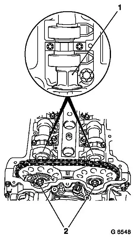
| 57. |
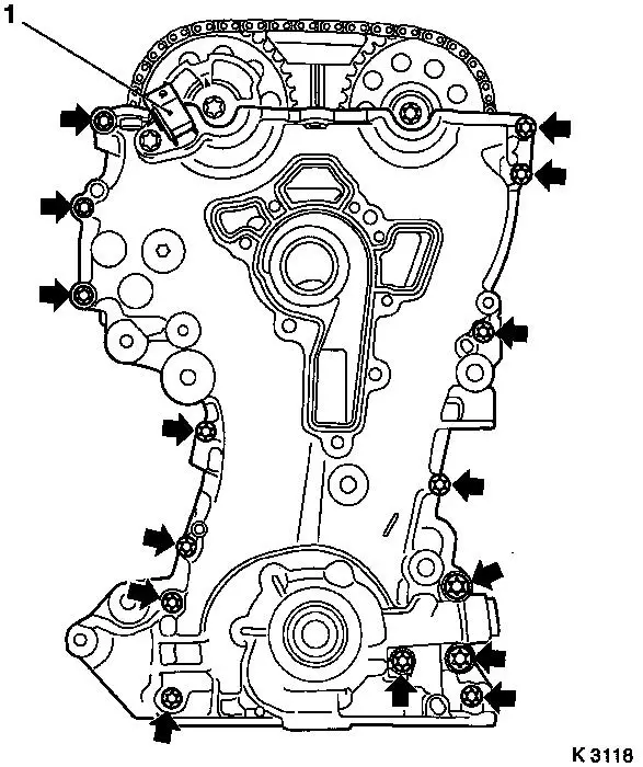
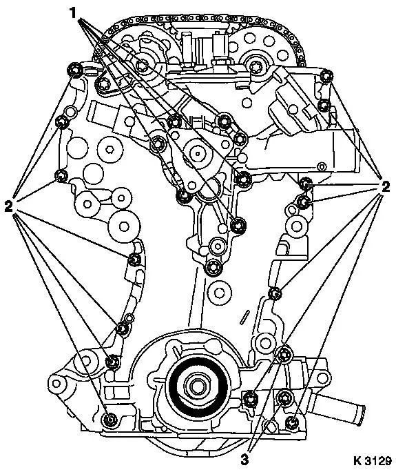
Attach timing case.
| • |
Screw in bolts
Note: Note tightening
sequence.
|
| • |
Tighten 5 bolts (M6) (1) 8 Nm
|
| • |
Tighten 14 bolts (M6) (2) 8 Nm
|
| • |
Tighten 2 bolts (M10) (3) 35 Nm
|
| • |
Attach coolant connection
| – |
Inspect visually, clean sealing surfaces
|
|
|
|
|
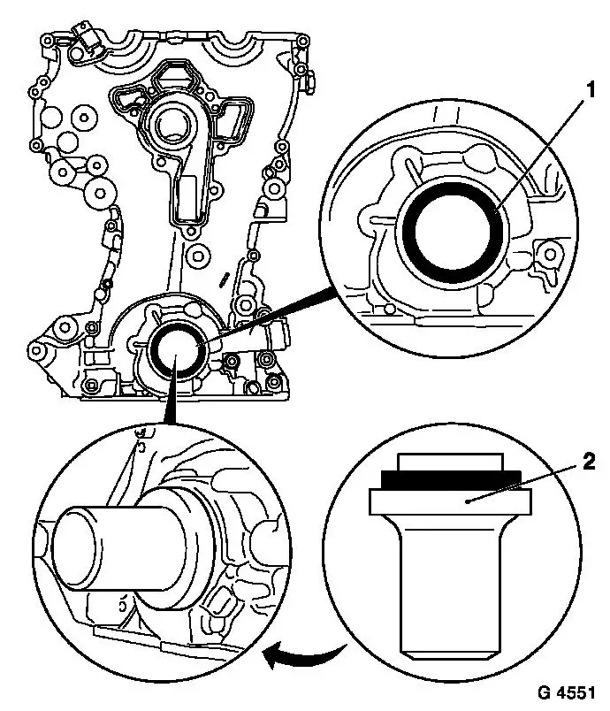
| 58. |
Replace crankshaft front seal ring (1)
| • |
Coat sealing lips with silicon grease
|
| • |
Drive in until flush using KM-960
|
|
| 59. |
Remove KM-952 KM-953
Note: Retaining tools
must not be used for counterholding
|
|
| 60. |
Attach crankshaft hub
Note: Second person
required
| • |
Note crankshaft hub installation position (2)
| – |
Marking must point upwards
|
|
| • |
Counterhold with KM-956-1 KM-956-2 (3)
|
| • |
Tighten bolt 150 Nm + 45°
|
| • |
Detach KM-956-1 KM-956-2
|
|
| 61. |
Attach crankshaft ribbed V-belt pulley (1)
| • |
Tighten 6 bolts 8 Nm
| – |
Counterhold at crankshaft hub bolt
|
|
|
| 62. |
Insert KM-953 into camshaft
grooves
|
|
|
| 63. |
Attach KM-954 (1)
| • |
Rotate phase sensor disk (2) until KM-954 can be attached to timing case
|
|
|
|
| 64. |
Fasten camshaft sprockets
Note: Tightening torque
of 10 Nm is used to secure the camshaft sprockets and the phase
sensor disk
| • |
Tighten 2 bolts (2) 10 Nm
Note: First tighten
intake camshaft sprocket bolt
| – |
Counterhold camshafts at hexagonal section (1)
|
|
|
| 65. |
Remove retaining tools
| • |
KM-952 , KM-953 , KM-954
|
|
| 66. |
Fasten camshaft sprockets
Note: Second person
required
| • |
Tighten 2 bolts 50 Nm + 60°
Note: First tighten
intake camshaft sprocket bolt
| – |
Counterhold camshafts at hexagonal section
|
|
|
|
|
| 68. |
Remove retaining tools
| • |
KM-952 , KM-953 , KM-954
|
|
| 69. |
Install oil intake pipe (1)
|
|
|
| 70. |
Attach oil pan
| • |
Align oil pan to cylinder block using straight edge
|
|
| 71. |
Attach closure bolt of crankshaft bearing bridge
|
| 73. |
Install crankshaft sensor
|
|
|
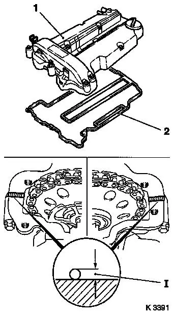
| 74. |
Attach cylinder head cover (1)
| • |
Replace gasket (2), seal rings
|
| • |
Apply sealant (dimension I = 2 mm)
Note: Complete assembly
operations within 10 minutes
|
| • |
Attach engine vent hose
|
|
| 75. |
Attach ignition module
|
| 76. |
Attach exhaust manifold
|
| 77. |
Attach exhaust manifold heat shield
|
| 78. |
Install oil dipstick guide tube
|
|
|
| 79. |
Attach coolant hoses
| • |
To exhaust recirculation valve
|
|
| 80. |
Attach wiring harness for engine management
| • |
Connect 14 wiring harness plugs
|
| • |
Attach engine control unit ground cable
|
| • |
On Z 10 XEP: Fit fuel rail cover
|
|
| 82. |
Attach alternator
| • |
Tighten 2 bolted connections 35
Nm
|
|
| 83. |
Connect engine wiring harness
| • |
Attach alternator wiring harness
|
| • |
Fasten starter wiring harness
|
|
| 84. |
Attach ribbed V-belt tensioner
| • |
Tighten bolt (M8) 20 Nm
|
| • |
Tighten bolt (M10) 55 Nm
|
|
| 85. |
Attach coolant pump ribbed V-belt pulley
|
| 86. |
Install ribbed V-belt
Note: Observe running
direction and installation position
| • |
Release ribbed V-belt tensioner
|
|
| 87. |
Attach right engine bracket
|
| 88. |
Attach flywheel
| • |
Clean 6 threads in crankshaft
|
| • |
Tighten 6 bolts 35 Nm + 60°
|
|
| 89. |
Attach clutch - see operation "Remove and install thrust plate
and clutch disk" in group "K"
|
| 90. |
Top up engine oil
| • |
Check engine oil level and correct if necessary
|
|
| 91. |
Detach engine from KM-412
Note: Second person
required
| • |
Undo 8 screw connections
|
|
| 93. |
Attach manual transmission to engine - see operation "J 3401 00
007 Manual transmission, attaching to / removing from engine"
|
| 94. |
Install engine - see operation "J 3401 00 Removing and
installing engine"
|
|
