|
Check oil pump (Z 14 XE with air conditioning LHD,
Z 16 YNG)
Note: KM-6394 must be used as of model year 04 instead of
KM-6169-1 .
Important: On vehicles as of
model year 04 with ESP - the steering angle sensor loses its basic
adjustment each time the battery is disconnected. It must be
recalibrated.
|
| 2. |
Disconnect battery
|
| 3. |
Remove engine cover.
| • |
Unscrew oil filler pipe cap
|
| • |
Screw on oil filler pipe cap
|
|
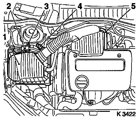
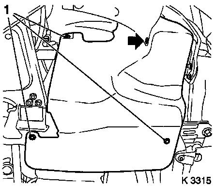
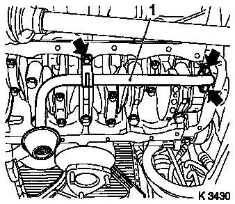
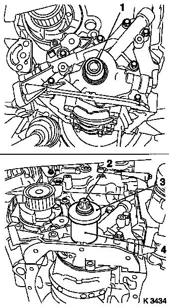
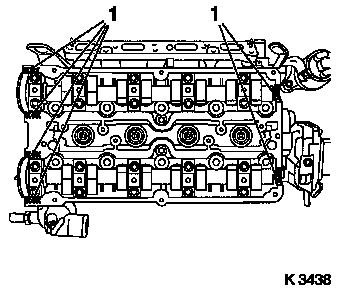
| 4. |
Remove air cleaner housing (1)
| • |
Disconnect wiring harness plug
| – |
Intake air temperature sensor (4), tank vent valve (2)
|
|
| • |
Detach engine vent hose (5)
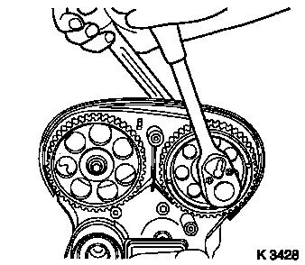
|
|
|
|
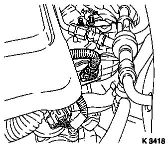
| 5. |
Remove ignition module
| • |
Disconnect wiring harness plug
|
Important: Do not tilt
|
| • |
Extract using KM-6009 (1)
|
|
| 6. |
Detach preheater hose for throttle valve module (2)
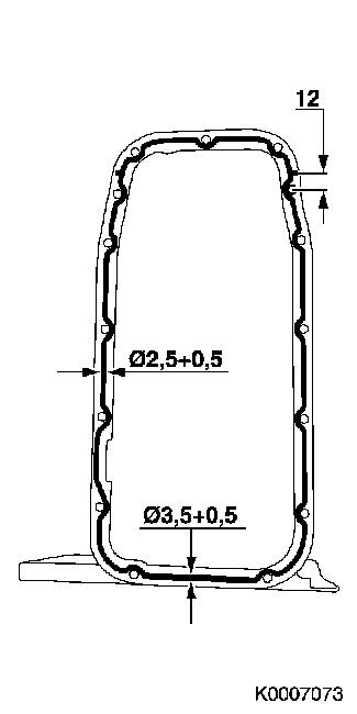
| • |
Place collecting basin underneath.
|
| • |
From thermostat housing
|
|
| 7. |
Disconnect wiring harness plug for coolant temperature sensor
(3)
| • |
Unclip from rear toothed belt cover
|
|
|
|
| 8. |
Remove cylinder head cover
| • |
Detach engine vent hose
|
|
|
|
| 9. |
Remove catalytic converter control oxygen sensor wiring harness
plug
| • |
Disconnect wiring harness plug
|
|
|
|
| 10. |
Loosen right front wheel.
|
| 12. |
Remove right front wheel.
|
| 14. |
Drain engine oil
| • |
Place collecting basin underneath.
|
|
| 15. |
Remove ribbed V-belt cover
|
|
|
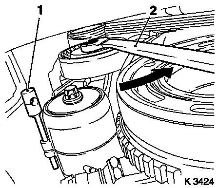
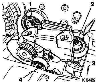
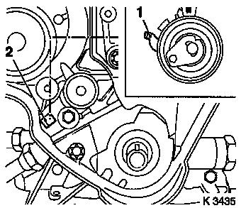
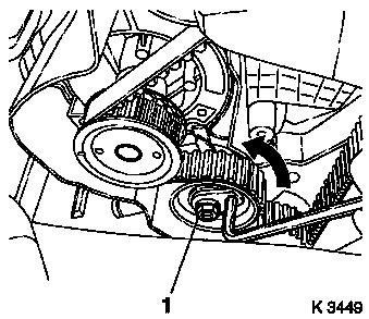
| 16. |
Remove ribbed V-belt
| • |
Tension ribbed V-belt tensioner in direction of arrow
| – |
Using KM-913-A (2) (SW 15)
|
|
| • |
Mark running direction.
|
|
|
|
| 17. |
Remove ribbed V-belt tensioner
| • |
Tension ribbed V-belt tensioner.
|
| • |
Release ribbed V-belt tensioner
|
|
|
|
| 18. |
Detach crankshaft ribbed V-belt pulley
| • |
Lever out front closure plug
|
|
|
|
| 19. |
Release lower part of toothed belt cover
| • |
Unclip from rear toothed belt cover
|
|
|
|
| 20. |
Install engine oil drain bolt
|
| 21. |
Loosen exhaust system
Important: When removing the
centre muffler, a catalytic converter, an exhaust manifold or an
exhaust manifold with catalytic converter, the exhaust system piece
remaining in the vehicle must be prevented from swinging
uncontrollably. The exhaust system piece with the flex pipe inside
can be secured for this purpose using suitable means, such as a
wire on the vehicle underbody. Bends in the flex pipe with an angle
as little as 5 – 10 degrees from the intended installation
position may result in damage with subsequent total failure of the
flex pipe.
|
| • |
Detach exhaust system
|
| • |
Detach front exhaust pipe
|
| • |
Suspend front exhaust pipe from left front axle body
|
|
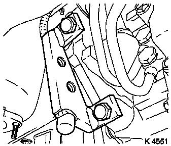
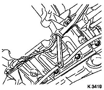
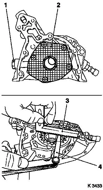
| 22. |
Remove oil pan
| • |
Lever out rear sealing plug (1)
|
| • |
Oil pump
| – |
Remove 3 bolts (arrows)
|
|
|
|
|
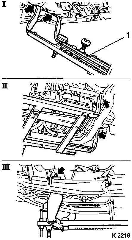
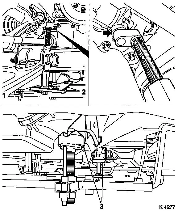
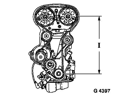
| 24. |
Attach KM-6169 (1)
| • |
Attach KM-6169 to left of front axle
body (arrows, illus. I)
Note: Guide pin must be
seated in bore in front axle body
|
| • |
Attach both right holders on the front axle body (arrows,
Illus. II).
Note: Guide pin must be
seated in bore in front axle body (arrow, Illus. III).
|
|
|
|
| 25. |
Install support
| • |
An KM-6169
| – |
Adjust bracket for support (2)
|
|
|
| 26. |
Adjust supports
| • |
Transmission side
Note: Turn spindles
until mounts (3) are positioned at the guide journals free of
play.
|
| • |
Engine timing side
| – |
Insert journal of the support in the bore of the cylinder block
without play (arrow)
|
|
|
|
|
| 28. |
Remove right engine damping block
| • |
Loosen engine bracket adapter
|
| • |
Loosen engine damping block
|
|
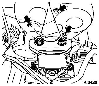
| 29. |
Remove upper part of toothed belt cover
| • |
Remove 3 bolts (arrows)
|
| • |
Unclip from rear toothed belt cover
|
|
|
|
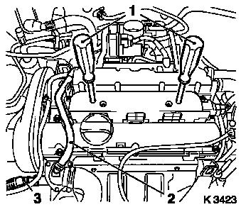
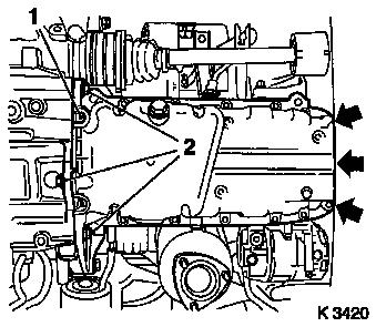
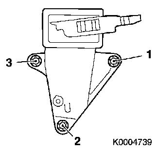
| 30. |
Remove camshaft sensor (1)
| • |
Disconnect wiring harness plug
|
|
| 31. |
Remove lower part of toothed belt cover
| • |
Unclip from rear toothed belt cover
|
|
|
|
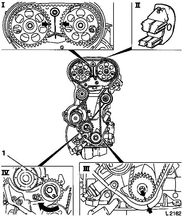
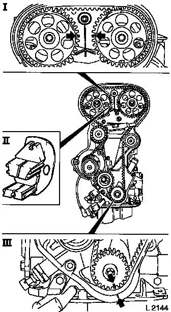
| 32. |
Set 1st cylinder to TDC of combustion stroke
| • |
Install crankshaft V-belt pulley bolt
|
| • |
Set crankshaft to mark.
| – |
Turn crankshaft evenly
Note: Marks on drive
gear toothed belt and rear toothed belt cover must align (III).
|
|
| • |
Fix camshaft sprockets in position.
Note: Marks must be
opposite one another and aligned with the top edge of the cylinder
head (I)
|
|
| 33. |
Remove toothed belt
| • |
Release toothed belt tension roller (IV)
Note: Mark running
direction.
| – |
Turn adjusting eccentric in direction of arrow (clockwise)
until pointer (1) of the toothed belt tension roller is located
just before left stop.
|
|
|
|
|
| 34. |
Remove camshaft sprockets
| • |
Remove 2 bolts
| – |
Counterhold camshafts at hexagonal section
|
|
|
|
|
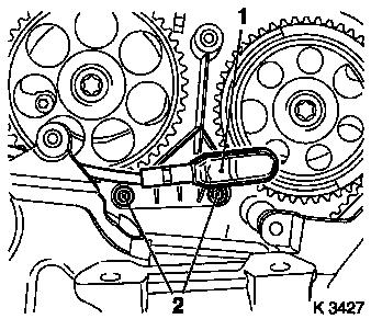
| 35. |
Remove intake side toothed belt guide roller (1)
|
| 36. |
Remove exhaust side toothed belt guide roller (2)
|
| 37. |
Remove right engine bracket (3)
|
| 38. |
Remove toothed belt tension roller (4)
|
|
|
| 39. |
Release rear toothed belt cover
|
| 41. |
Remove toothed belt drive pulley
| • |
Counterhold with KM-911
|
| • |
Unscrew crankshaft ribbed V-belt pulley bolt
|
| • |
Remove toothed belt drive pulley
|
|
| 42. |
Remove rear of toothed belt cover
|
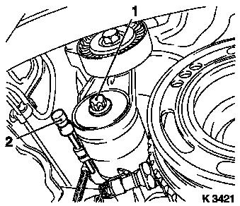
| 43. |
Remove oil intake pipe (1)
| • |
Remove 3 bolts (arrows)
|
|
|
|
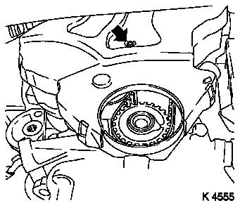
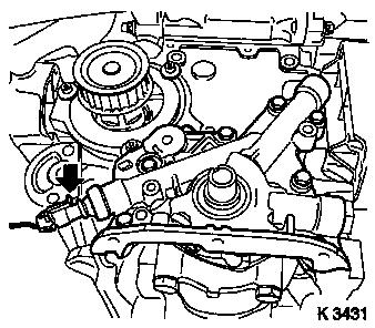
| 44. |
Remove oil pump
| • |
Disconnect oil pressure switch wiring harness plug (arrow)
|
|
|
|
| 45. |
Remove front crankshaft seal ring
Important: Do not damage sealing
surface.
|
| • |
Lever out seal ring
|
|
| 46. |
Disassemble oil pump
| • |
Detach oil pump cover (2)
|
| • |
Remove inner and outer cusp (gear pair)
|
|
| 47. |
Remove oil pump pressure regulating valve
|
| 48. |
Inspect components
| • |
Oil pump housing, inner rotor, outer rotor, oil pump cover
|
|
| 49. |
Check oil pump
Important: The bevel running
around the outside edge of the outer cusp must face the oil pump
housing.
|
| • |
Insert inner and outer cusp (gear pair)
|
| • |
Measure gap
Note: The maximum
amount of play that is permitted between the gear pair and the top
edge of the oil pump housing is 0.03 to 0.10 mm.
| – |
With straightedge (3), feeler gauge (4)
|
|
|
|
|
| 50. |
Install oil pump pressure regulating valve
|
| 51. |
Assemble oil pump
| • |
Insert inner and outer rotor
Important: The bevel running
around the outside edge of the outer rotor must face the oil pump
housing.
|
| – |
Coat with engine oil
|
|
|
| 52. |
Clean sealing surfaces
| • |
Oil pump, cylinder block, oil pan, oil suction pipe, cylinder
head, cylinder head cover
|
|
| 53. |
Inspect components
| • |
Ribbed V-belt, ribbed V-belt tensioner, ribbed V-belt pulley,
toothed belt drive, camshafts, oil pump, oil suction pipe
|
|
| 55. |
Install oil pump
| • |
Connect wiring harness plug to oil pressure switch.
|
|
| 56. |
Install front crankshaft seal ring
| • |
Coat seal lip with grease
|
| • |
Attach KM-6010 to crankshaft journal
(1)
|
| • |
Slide seal ring over KM-6010
|
| • |
Pull in front crankshaft seal ring
| – |
With KM-6010 (4), bolt (2) and
crankshaft ribbed V-belt pulley washer (3)
|
|
|
|
|
| 57. |
Install rear toothed belt cover
| • |
Tighten lower bolts ( 6 Nm )
|
|
| 58. |
Install toothed belt drive pulley
|
| 60. |
Fasten rear toothed belt cover
|
| 61. |
Install toothed belt tension roller
Important: Detent lever (1) of
toothed belt tension roller must engage in guide web (2) of oil
pump.
|
| • |
Bolt in bolt
Note: Adjust toothed
belt tension before tightening bolt.
|
|
|
|
| 62. |
Install right engine bracket
| • |
Tighten bolts ( 65 Nm + 45° +
15° )
Note: The rotating
angle to be applied must be set by eye.
|
| • |
Note tightening sequence.
|
|
|
|
| 63. |
Install intake side toothed belt guide roller
Important: The toothed belt guide
roller with the greater diameter is installed at the intake
side.
|
| • |
Tighten bolt 25 Nm
|
|
| 64. |
Install exhaust side toothed belt guide roller
|
| 65. |
Install camshaft sprockets
Note: Attach camshaft
sprocket with cylinder recognition to exhaust camshaft.
| • |
Renew bolts
Note: 2nd mechanic
required.
|
| • |
Tighten bolts ( 50 Nm + 60°+
15° )
| – |
Counterhold camshafts at hexagonal section
|
|
|
| 66. |
Fix camshaft sprockets in position.
| • |
Use KM-852
| – |
Turn the camshafts at hexagonal section
|
|
|
| 67. |
Check that 1st cylinder is at TDC
| • |
Install crankshaft V-belt pulley bolt
|
| • |
Set crankshaft to mark.
| – |
Turn crankshaft evenly
Note: Marks on drive
gear toothed belt and rear toothed belt cover must align.
|
|
|
| 68. |
Install toothed belt
Note: Pay attention to
direction of travel and timing marks.
| • |
Position toothed belt
Note: Tensioned side
must be taut (I).
|
|
|
|
| 69. |
Tension toothed belt
| • |
Tension toothed belt tension roller
| – |
Turn adjusting eccentric in direction of arrow (anticlockwise)
until pointer of the toothed belt tension roller is located just
before left stop
|
|
| • |
Fasten toothed belt tension roller bolt (1)
|
|
|
|
| 71. |
Timing, Check
| • |
Turn crankshaft (720°)
| – |
At crankshaft ribbed V-belt pulley bolt
Note: In direction of
engine rotation.
|
|
| • |
Set crankshaft to mark.
Note: Marks on drive
gear toothed belt and rear toothed belt cover must align (III).
|
| • |
Use KM-852 (II)
Note: Marks must be
opposite one another and aligned with the top edge of the cylinder
head (I)
|
|
|
|
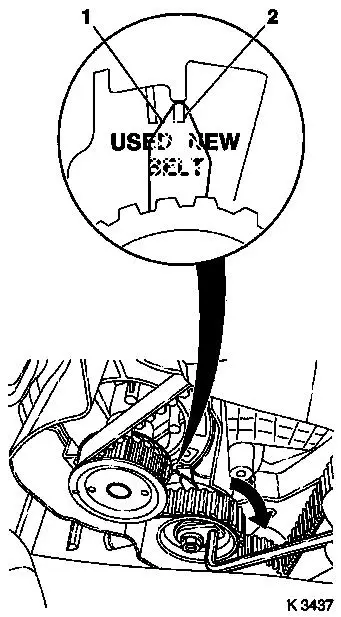
| 73. |
Adjust toothed belt tension
| • |
Release toothed belt tension roller
|
| • |
Turn adjustment eccentric in the direction of the arrow
(clockwise) until pointer (1) is aligned with the notch mark at the
toothed belt tension roller (2).
| – |
Adjust used toothed belts to the marking USED
|
| – |
Adjust new toothed belts to the marking NEW
|
|
| • |
Tighten toothed belt tension roller bolt 20 Nm
|
|
| 74. |
Check toothed belt tension
| • |
Turn crankshaft (720°)
Note: Pointers on the
toothed belt tension roller and notch mark must align.
| – |
Adjust used toothed belts to the marking USED
|
| – |
Adjust new toothed belts to the marking NEW
|
|
|
|
|
| 76. |
Attach camshaft sensor
| • |
Insert bolts with locking compound (red)
|
|
| 77. |
Install lower part of toothed belt cover
| • |
Clip to rear toothed belt cover
|
|
| 78. |
Connect wiring harness plug from camshaft sensor
| • |
Connect wiring harness plug from camshaft sensor.
|
|
| 79. |
Install upper part of toothed belt cover
| • |
Clip to rear toothed belt cover
|
|
| 80. |
Install right engine damping block
| • |
Fasten engine bracket adapter
| – |
Tighten bolts ( 60 Nm + 30° -
45° )
|
|
| • |
Fasten engine damping block
|
|
| 85. |
Install oil intake pipe
|
| 86. |
Install oil pan
Important: Complete installation
work within 10 minutes
|
| • |
Apply sealant
|
| • |
Insert rear closure plug
|
|
|
|
| 87. |
Attach exhaust system
| • |
Attach oxygen sensor (catalytic converter control) cable to
intake manifold support and fold upwards
|
|
| 88. |
Install ribbed V-belt tensioner
| • |
Tension ribbed V-belt tensioner.
|
|
| 89. |
Attach crankshaft ribbed V-belt pulley
| • |
Tighten bolt 95 Nm + 30° +
15°
|
| • |
Insert front sealing plug
|
|
| 90. |
Install ribbed V-belt
Note: Note running
direction and installation position
| • |
Release ribbed V-belt tensioner
|
|
| 91. |
Install ribbed V-belt cover
|
| 93. |
Mount right front wheel.
|
| 95. |
Fasten right front wheel.
|
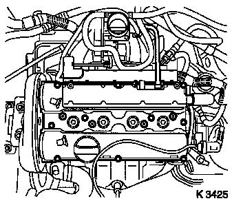
| 96. |
Install cylinder head cover
Important: Complete installation
work within 10 minutes
|
| • |
Apply sealant to sealing surfaces(1)
|
| • |
Attach engine vent hose
|
| • |
Connect cable harness plug of oxygen sensor, mixture
regulation, heated
|
|
|
|
| 97. |
Install catalytic converter control oxygen sensor wiring
harness plug
| • |
Connect wiring harness plug.
|
|
| 98. |
Attach preheater hose for throttle valve module
| • |
Connect wiring harness plug for coolant temperature sensor
|
|
| 99. |
Install ignition module
| • |
Connect wiring harness plug.
|
|
| 100. |
Install air cleaner housing
| • |
Attach engine vent hose
|
| • |
Connect wiring harness plug.
|
|
| 101. |
Install engine cover.
| • |
Unscrew oil filler pipe cap
|
| • |
Screw on oil filler pipe cap
|
|
| 103. |
Calibrate steering angle sensor
| • |
Switch on ignition
Note: Rotate the
steering wheel one time from its right-hand to its left-hand
stop.
|
|
| 104. |
Top up engine oil
| • |
Observe specified engine oil quantity
|
| • |
Start engine and allow to run until oil pressure telltale
extinguishes.
|
| • |
Check engine oil level, if necessary correct.
|
|
| 105. |
Top up coolant
| • |
Observe specified coolant quantity
|
|
| 106. |
Program volatile memories
|
|