|
J496000 Injector Nozzles, Remove and Install (Y 17
DTL, without AC, LHD)
|
1. Open bonnet
|
|
Caution!
On vehicles from model year 04 with ESP - the steering angle
sensor loses its basic adjustment each time the battery is
disconnected. It must be recalibrated.
2. Disconnect battery
|
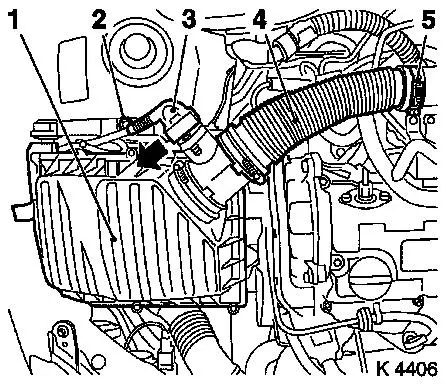
3. Remove air cleaner housing (1)
- Remove wiring harness plug for hot film mass air flow meter
(3)
- Release in direction of arrow
- Remove air intake hose (4)
- Remove bolt (2)
|
|
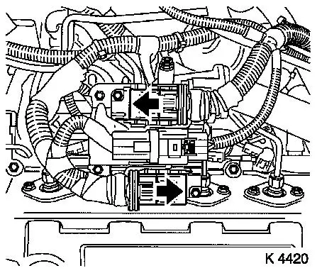
4. Remove wiring harness plug for
engine control unit
- 3 off
- Release 2 wiring harness plugs in direction of arrow
|
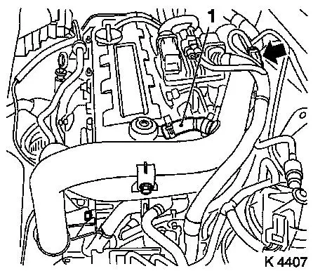
5. Remove air intake pipe
- Remove 3 bolts
- Remove vent hose (1)
- Release clamp
- Unclip wiring harness
|
|
|
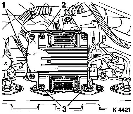
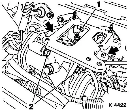
6. Remove engine control unit
- Remove wiring harness plug bracket (1)
- Unscrew 2 bolts (2), 2 nuts (3)
|
|
|
7. Remove engine control unit
bracket
- Unscrew 2 bolts (2), nut (1)
- Unclip wiring harness
|
|
8. Remove right rear engine transport
shackle
9. Loosen left rear engine transport shackle
10. Remove injection lines
|
11. Remove outer injector nozzle
seals
|
|
12. Remove oil dipstick guide tube
bracket
|
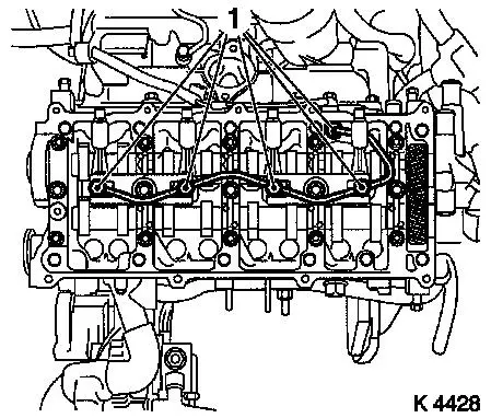
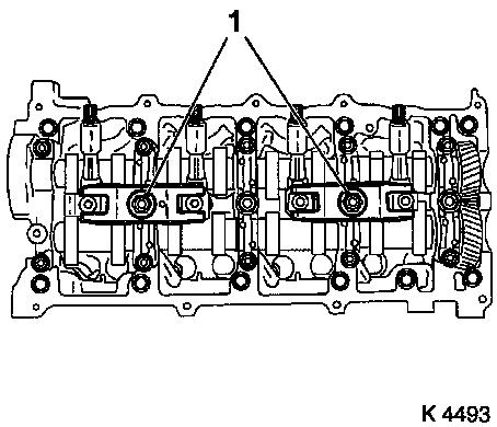
13. Remove camshaft housing cover
- Unscrew 9 bolts (1), 3 studs (2)
|
|
14. Remove camshaft housing cover
- Note! 2. mechanic
- Carefully push injection line to rear
|
15. Detach inner oil leak line
- Unscrew 5 banjo bolts (1)
- Note! Note sealing rings
|
|
|
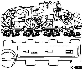
16. Remove injector nozzles
Caution!
Ensure that upon removal of injector nozzles heat protection
sleeves remain in their position on the cylinder head.
Otherwise, heat protection sleeves must
be removed completely and installed again using new seal rings.
This is the only way to ensure that no coolant can reach the
combustion chamber, which would inevitably cause engine damage.
Replace heat protection sleeves – see operation "Replace heat
protection sleeves" in document "Check and measure cylinder
head".
- Remove injection nozzle bracket (1)
- Remove injector nozzles
|
|
|
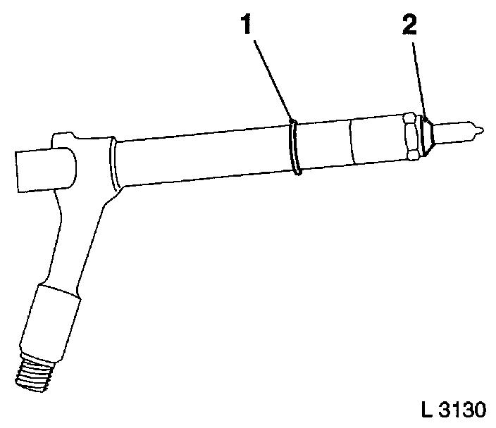
17. Install injector nozzles
- Replace seal rings (1)
- Replace copper seal rings (2)
- Insert injection nozzles in cylinder head.
- Install injector nozzle bracket (22.1 Nm/16.3 lbf. ft.)
|
|
18. Attach inner oil leak line
- Renew seal rings
- Tighten banjo bolt (14.7 Nm/10.8 lbf. ft.)
|
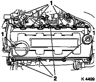
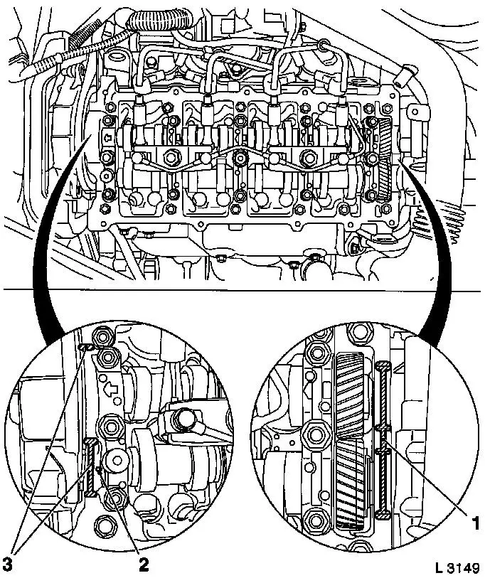
19. Install camshaft housing cover.
- Replace gasket
- Apply adhesive sealant compound (white)
- Caution! Oil return bore (2) must not be covered with adhesive
sealing compound or by the camshaft housing cover gasket
|
|
20. Install camshaft housing cover
- Note! 2. mechanic
- Carefully push injection line to rear
21. Tighten camshaft housing cover
- Tighten bolts, studs (9.8 Nm/7.2 lbf. ft.)
22. Install oil dipstick guide tube
bracket
23. Install outer injector nozzle
seals
- Replace seals
- Tighten bolts
24. Install injection lines
- Tighten union nuts (22.5 Nm/16.6 lbf. ft.)
25. Fasten left rear engine transport
shackle
- Tighten bolts (20 Nm / 15 lbf. ft.)
26. Install right rear engine transport
shackle
- Tighten bolt (20 Nm / 15 lbf. ft.)
27. Install engine control unit
bracket
- Tighten bolts
- Attach wiring harness
28. Install engine control unit
- Tighten bolts, nuts (5.9 Nm/4.4 lbf. ft.)
- Install wiring harness plug bracket
29. Install air intake pipe
- Tighten bolts
- Fasten clamp
- Attach engine vent hose
- Attach wiring harness
30. Attach engine control unit wiring
harness plug
31. Install air cleaner housing
- Tighten bolt
- Fasten air intake hose.
- Tighten clamp (3.5 Nm / 2.6 lbf. ft.)
- Connect wiring harness plug to hot film mass air flow
meter
32. Connect battery
33. Calibrate steering angle sensor
Note: Rotate the
steering wheel one time from its right-hand to its left-hand
stop.
34. Program volatile memories
35. Close bonnet
|
