|
Overhaul drive shaft assembly (AF13-II)
 Remove Remove
|
| 1. |
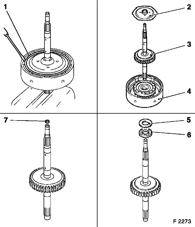
Remove assembly, drive shaft with multi-plate clutch C2 
|
| 2. |
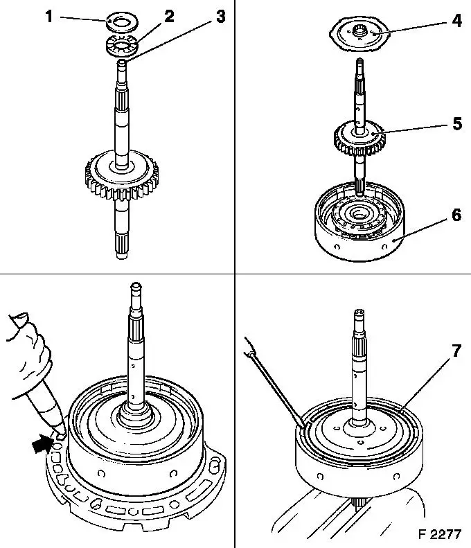
Remove retaining ring (1) from multi-plate clutch C2 with
suitable screwdriver
| • |
Clamp assembly, drive shaft with multi-plate clutch C2, in
vice
|
|
| 3. |
Remove flange (2) and multi-plate clutch assembly C2 (4) from
drive shaft (3)
|
| 4. |
Remove friction washer (5) and axial needle bearing (6) from
drive shaft
|
| 5. |
Remove slotted seal ring (7)
|
|
|
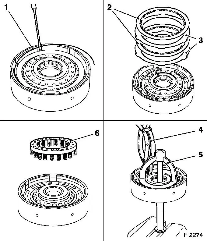
| 6. |
Remove retaining ring (1) for multi-plate clutch C2 with a
suitable screwdriver
Note: If necessary,
remove topmost liner plate to obtain access to retaining ring.
|
| 7. |
Remove liner plates (2) and steel plates (3)
|
| 8. |
Remove retaining ring with KM-396
(4)
| • |
Fit clutch tensioner KM-J-23078-A (5)
and clamp nut in vice for tensioning
|
| • |
Expose retaining ring
| – |
Rotate housing for multi-plate clutch C2 with clutch tensioner
KM-J-23078-A (compress release
springs)
|
|
|
| 9. |
Release clutch tensioner KM-J-23078-A
and remove
|
| 10. |
Remove return spring assembly (6)
|
|
 Install
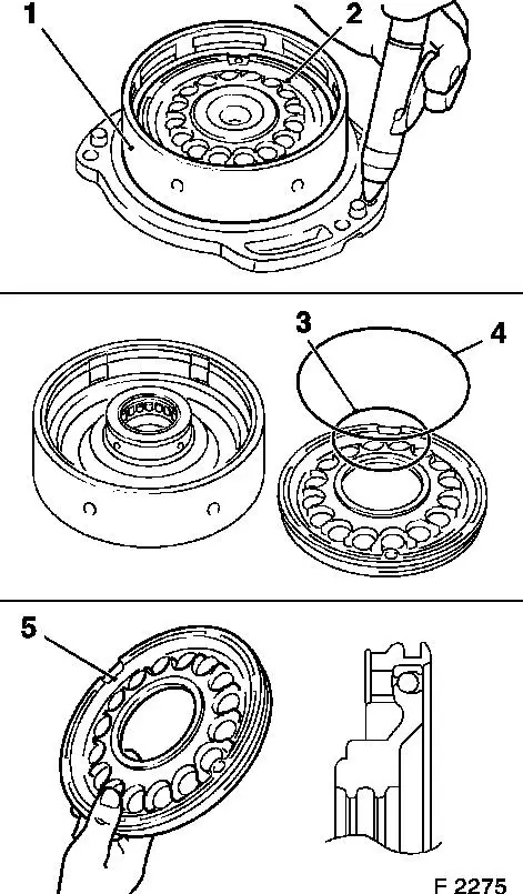
| 11. |
Insert housing with piston for multi-plate clutch C2 (1) in
fluid pump
Note: When inserting in
fluid pump, ensure that the slotted seal rings (x 2) are not
damaged.
|
| 12. |
Remove piston for multi-plate clutch C2 (2)
| • |
Blow in air at low pressure
|
| • |
Replace piston seal rings (3) and (4)
Note: Coat with
transmission fluid before installation.
|
|
| 13. |
Check lock ball of piston (5) for multi-plate clutch C2
| • |
Check whether lock ball can move by shaking the piston
|
|
| 14. |
Check return spring assembly for damage
Note: Replace if
necessary.
|
| 15. |
Check sliding surfaces of the steel and liner plates for damage
and wear
Note: Replace if
necessary.
Place new liner plates in transmission fluid for at least 2 hours
before installation
|
|
|
|
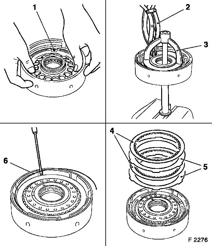
| 16. |
Insert piston C2 (1) into housing for multi-plate clutch C2
| • |
Use new O-rings
Note: Do not damage
O-rings.
|
|
| 17. |
Place return spring assembly on piston C2
| • |
Attach new retaining ring
|
| • |
Attach KM-J-23078-A (3) and compress
return springs
|
| • |
Insert retaining ring with KM-396
(2)
|
| • |
Relieve stress on KM-J-23078-A and
detach
|
|
| 18. |
Place steel plate (5) and liner plate (4) respectively
alternately on piston C2
Note: Number of steel
and liner plates
|
| 19. |
Insert new retaining ring (6) with screwdriver
Note: Ensure it is
correctly seated.
|
|
|
| 20. |
Attach output shaft (2), friction washer (1) and slotted seal
ring (3) to drive shaft
|
| 21. |
Assemble multi-plate clutch C2 (6), drive shaft (5) and flange
(4) assembly
|
| 22. |
Fit new retaining ring (7) with screwdriver
|
| 23. |
Insert assembly, drive shaft with multi-plate clutch C2 in oil
pump
Note: Do not damage
seal rings.
|
| 24. |
Check operation of piston C2
| • |
Blow compressed air into bore in fluid pump (arrow)
|
|
|
| 25. |
Remove drive shaft assembly with multi-plate clutch C2 from
fluid pump
|
| 26. |
Install assembly, drive shaft with multi-plate clutch C2
|
|
