|
Replace bearing in transmission housing (F23)
 Remove Remove
| 1. |
Dismantle transmission
|
| 2. |
Check main shaft and intermediate shaft bearing for damage
| • |
If necessary, replace bearing
|
|
|
| 3. |
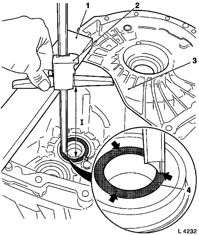
When replacing main shaft bearing: determine installed position
of old main shaft bearing in transmission housing
Note: Ensure that the
main shaft bearing in the transmission housing is not resting on
the workbench during measurement. Support the transmission housing
so that the inner ring of the main shaft bearing hangs free.
| • |
Place KM-621-23 (1) on transmission
housing (3)
|
| • |
Determine distance (I) from inner ring of main shaft bearing to
top edge of KM-621-23
| – |
Use a standard commercial digital depth micrometer (2)
Note: Micrometer range
at least 250 mm, 0.01 mm graduations
|
| – |
Perform measurement 3 times - space measuring points evenly
around inner ring (arrows)
|
| – |
Add all measured values together
|
| – |
Divide by the number of measurements
|
| – |
Note down the average
Note: The table below
is a specimen calculation. You can enter the actual measurement
results in the blank column on the right of the printout and
perform the calculation there.
|
Example
=
|
|
|
Your values
|
|
1st measurement
|
187.02mm
|
+
|
1st measurement
|
|
2nd measurement
|
187.06mm
|
+
|
2nd measurement
|
|
3rd measurement
|
187.05mm
|
=
|
3rd measurement
|
|
Total
|
561.13mm
|
:3=
|
Total
|
|
Average
|
187.04mm
|
|
Average
|
|
|
|
|
|
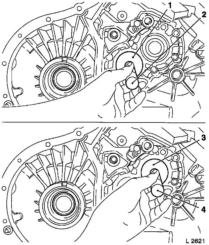
| 4. |
When replacing the main shaft bearing: remove main shaft
bearing from transmission housing
| • |
Knock out with KM-6122 (1) and KM-523-1 (2)
|
|
| 5. |
When replacing the drive shaft bearing: remove drive shaft
bearing from transmission housing
| • |
Knock out with KM-6123 (3) and KM-523-1 (4)
|
|
|
|
| 6. |
When replacing the main shaft bearing: install new main shaft
bearing in transmission housing
| • |
Knock out with KM-6122 (1) and KM-523-1 (2)
|
|
| 7. |
When replacing the drive shaft bearing: install new drive shaft
bearing in transmission housing
| • |
Knock out with KM-6123 (3) and KM-523-1 (4)
|
|
|
|
| 8. |
When replacing the drive shaft bearing: determine installed
position of new main shaft bearing in transmission housing
Note: Ensure that the
main shaft bearing in the transmission housing is not resting on
the workbench during measurement. Support the transmission housing
so that the inner ring of the main shaft bearing hangs free.
| • |
Place KM-621-23 (1) on transmission
housing (3)
|
| • |
Determine distance (I) from inner ring of main shaft bearing to
top edge of KM-621-23
| – |
Use a standard commercial digital depth micrometer (2)
Note: Micrometer range
at least 250 mm, 0.01 mm graduations
|
| – |
Perform measurement 3 times - space measuring points evenly
around inner ring (arrows)
|
| – |
Add all measured values together
|
| – |
Divide by the number of measurements
|
| – |
Note down the average
Note: The table below
is a specimen calculation. You can enter the actual measurement
results in the blank column on the right of the printout and
perform the calculation there.
|
Example
=
|
|
|
Your values
|
|
1st measurement
|
187.02mm
|
+
|
1st measurement
|
|
2nd measurement
|
187.06mm
|
+
|
2nd measurement
|
|
3rd measurement
|
187.05mm
|
=
|
3rd measurement
|
|
Total
|
561.13mm
|
:3=
|
Total
|
|
Average
|
187.04mm
|
|
Average
|
|
|
|
|
| 9. |
Calculate the dimensional difference between the installed
positions of the new/old main shaft bearing inner rings
| • |
Calculate the difference between the averages
| – |
Subtract the average noted down for the new bearing from the
average noted down for the old bearing
Note: If the difference
exceeds +0.02/-0.06mm, the pressure collar must be adjusted.
Note: The table below
is a specimen calculation. You can enter the actual measurement
results in the blank column on the right of the printout and
perform the calculation there.
|
Average for old bearing
|
187.04mm
|
-
|
Average for old bearing
|
|
|
mm
|
-
|
|
Average for new bearing
|
187.16mm
|
=
|
Average for new bearing
|
|
|
mm
|
=
|
|
Difference
|
-0.12mm
|
|
Difference
|
|
|
mm
|
|
|
|
|
|
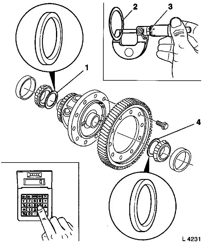
| 10. |
If necessary, reset pressure collar
| • |
Remove differential gear tapered roller bearing 
|
| • |
Replace 2 shims (1) and (4)
Note: If the
dimensional difference is positive, a shim (4) that is thicker by
the same amount must be selected at the transmission housing side.
If the dimensional difference is negative, an appropriately thinner
shim must be used. The total thickness of the two shims (1) and (4)
must remain constant, since they determine the pretension of the
differential gear tapered roller bearing. For this reason, when a
thicker shim (4) is used at the transmission housing side, a shim
that is thinner by the same amount must be installed at the clutch
housing side (1). When a thinner shim is used at the transmission
housing side an appropriately thicker shim must be installed at the
clutch housing side.
Note: The shims can be
obtained from "Aftersales". The thickness of the shims (2) must be
determined with a micrometer (3) as they are not marked.
Note: The table below
contains a few examples from the range of shims that can be
supplied. When adjusting, the shims must be selected to achieve the
smallest tolerance possible. Undamaged used shims can be
re-used.
|
Difference in dimensions
|
Shim (on transmission housing side)
|
Shim (on clutch housing side)
|
| |
old
|
new
|
old
|
new
|
|
+ 0.25mm
|
0.90mm
|
1.15mm
|
0.75mm
|
0.50mm
|
|
- 0.20mm
|
0.90mm
|
0.70mm
|
0.75mm
|
0.95mm
|
|
- 0.13mm
|
0.90mm
|
0.75mm
|
0.75mm
|
0.90mm
|
|
-0.12mm
|
0.90mm
|
0.80mm
|
0.75mm
|
0.85mm
|
|
|
|
 Install
| 11. |
Install differential gear tapered roller bearing
|
| 12. |
Assemble transmission
|
|
