|
Remove and install manual transmission (F 23)
 Remove Remove
| 1. |
Detach crash box
Note: The fuel system
remains closed.
|
| 2. |
Seal off brake fluid reservoir
| • |
Seal off brake fluid reservoir with MKM-558-10
|
|
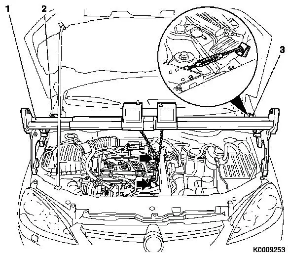
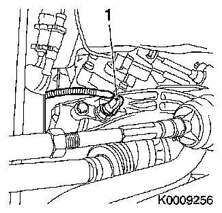
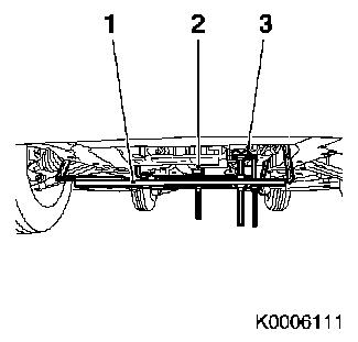
| 3. |
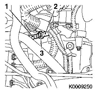
Detach pressure line (1) from transmission
Note: Collect escaping
brake fluid
| • |
Detach retaining clip (3) and pull pressure line out of
connector for pressure line to central release (2)
|
| • |
Drive retaining clip into connector
|
|
|
|
|
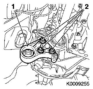
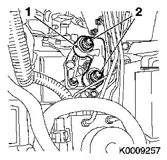
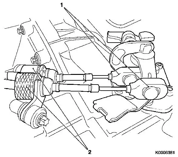
| 4. |
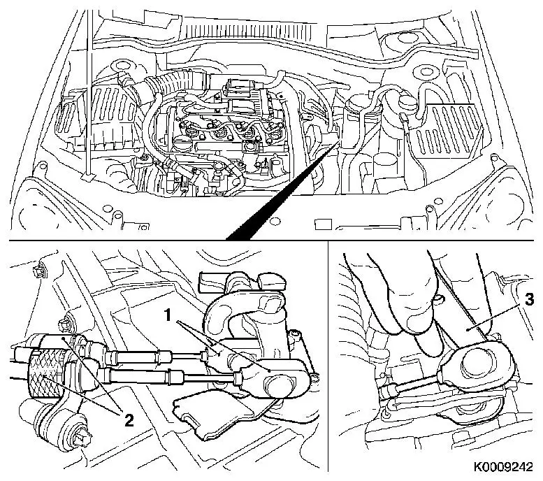
Detach shift cables (1) from transmission
| • |
Unclip shift cables from guide lever with KM-6042 (3)
|
| • |
Unclip 2x out of counterhold
Note: Pull back sleeve
(2) and pull cable from counterhold. Note cable arrangement.
|
|
|
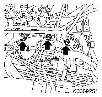
| 5. |
Release transmission at top
| • |
Unscrew 3x bolt (arrows)
Note: Note different
bolt lengths
|
|
|
|
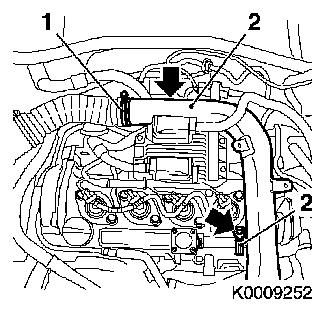
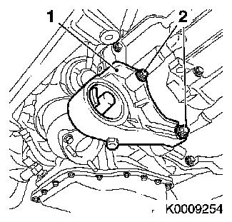
| 6. |
Detach intake pipe (2)
| • |
Unscrew 2x bolt (arrows)
|
| • |
Undo 2 clamps (1) and (3)
|
|
|
|
|
| 7. |
Attach engine bridge MKM-883-1
(1).
Note: Follow
manufacturer's instructions. 2nd mechanic required.
| • |
Prevent from tilting with MKM-883-3
(2) and (3)
|
|
Warning: Follow manufacturer's
instructions.
|
| 8. |
Attach engine
| • |
Attach MKM-883-1 to 2 engine
transport shackles (arrows)
|
| • |
Tension hoist chains but do not raise engine
|
|
|
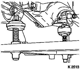
| 9. |
Attach KM-6169
Insert KM-6169 into front axle body
Note: The drive unit
must be aligned to the front axle body using KM-6169 in order to ensure correct alignment of the
drive unit after releasing the bolts for the right and left engine
damping blocks.
| • |
Pins must be seated in the guide holes of the front axle
body
|
| • |
Tighten 2 bolts for adjustment rails
|
| • |
Twist up the rear support bearing until it rests against the
guide pins of the rear engine damping block bracket
Note: The guide pins
must sit in the support bearing without play.
|
| • |
Twist up the front support bearing until it rests against the
guide pins of the front engine damping block bracket
Note: The guide pins
must sit in the support bearing without play.
|
|
|
|
| 10. |
Remove front axle body
|
| 11. |
Detach front engine damping block (1)
|
|
|
| 12. |
Remove rear engine damping block bracket (1)
|
|
|
| 13. |
Disconnect wiring harness plug for reversing lamps switch
(1)
|
|
|
| 14. |
Detach left axle shaft
Note: Place collecting
basin underneath - fluid escapes
Note: Axle shaft
remains in wheel hub.
| • |
Attach axle shaft to vehicle underbody
|
|
| 15. |
Detach right axle shaft
Note: Axle shaft
remains in wheel hub.
| • |
Attach axle shaft to vehicle underbody
|
|
| 16. |
Remove intermediate shaft
Note: Place collecting
basin underneath - fluid escapes
|
| 17. |
Loosen left engine damping block (1)
|
|
|
| 18. |
Lower drive mechanism
Note: Lower drive
mechanism approx. 5 cm. Do not damage attaching parts.
|
| 19. |
Detach left engine damping block bracket (1)
|
|
|
|
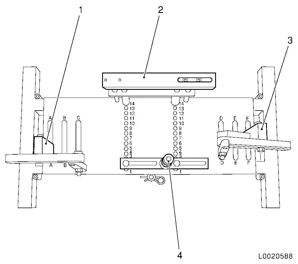
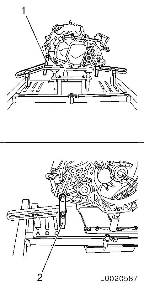
| 20. |
Position transmission holder DT-47648
on KM-904 and preinstall as shown in the
illustration:
|
Component
|
Position on base plate
|
Designation
|
|
DT-47648-2
(4)
|
2
|
Clutch housing support
|
|
DT-47648-3
(2)
|
14
|
Transmission housing support
|
|
DT-47648-5 left
(1)
|
A
|
Support with rear transmission swivel arm
|
|
DT-47648-5 right
(3)
|
F
|
Support with front transmission swivel arm
|
|
|
Important: It is important that
the manufacturer's instructions for transmission holder DT-47648 are followed.
|
| 21. |
Attach transmission holder DT-47648
to transmission
Note: Before placing in
position, slacken all bolt connections of the swivel arms and
supports as far as the base plate. Adjust the supports using the
spindles until they are as low as possible.
| • |
Position transmission holder DT-47648
and supports under the transmission
|
| • |
Tighten the bolt connections of the supports
|
| • |
Attach swivel arms (1) and (2) to transmission
|
| • |
Tighten bolt connections of swivel arms, starting from the
transmission and going as far as the base plate
Note: Align the swivel
arms so that as little leverage as possible is created.
|
|
|
|
|
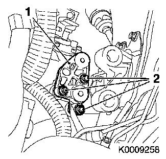
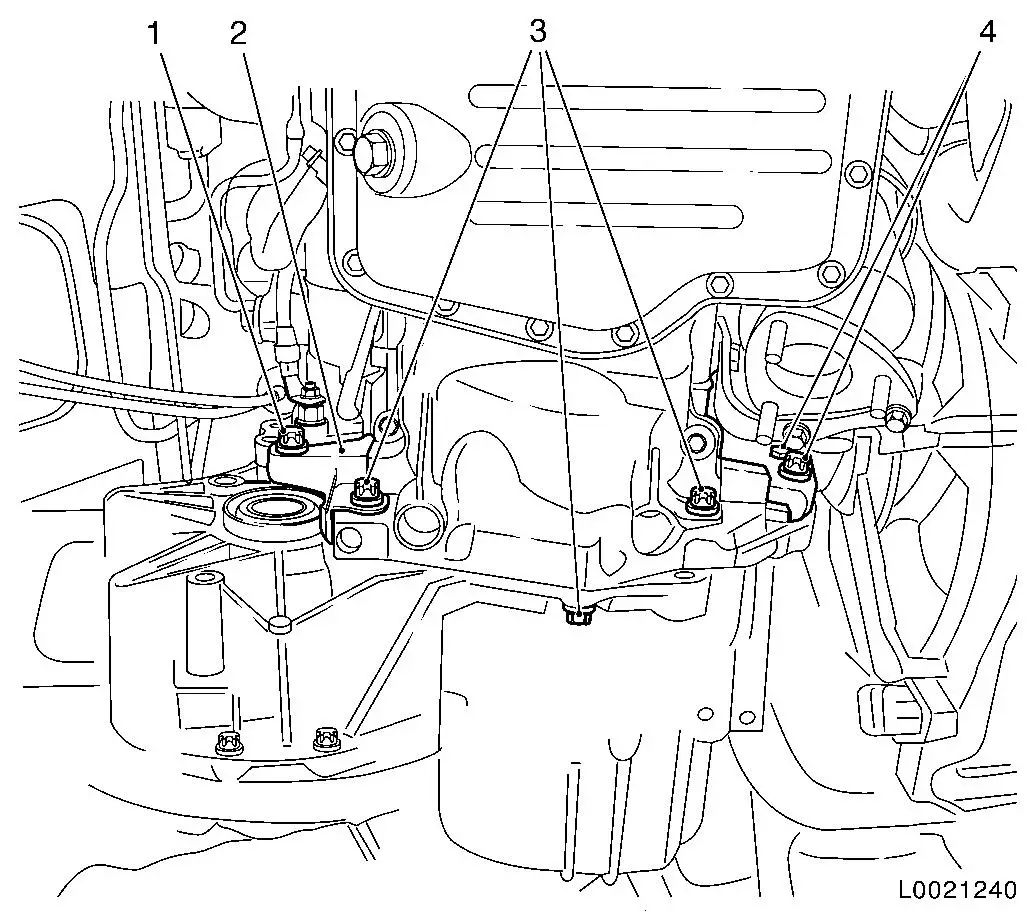
| 22. |
Remove transmission
| • |
Unscrew 3x bolts, transmission to engine oil pan (3)
|
| • |
Unscrew 3x bolts (1) and (4), transmission to cylinder
block
Note: Note different
bolt lengths
|
| • |
Remove flywheel cover (2)
|
|
|
Important: Do not damage
attaching parts when laying transmission down.
|
| 23. |
Detach transmission from DT-47648
Note: 2nd person
required
| • |
Carefully lay transmission down
|
|
 Install
| 24. |
Attach transmission to DT-47648
Note: 2nd person
required
|
| 25. |
Install transmission with DT-47648
| • |
Raise and align transmission
|
| • |
Place transmission so that it is in even contact with the
engine
Note: Ensure that it is
properly seated
|
|
|
| 26. |
Install transmission
| • |
Tighten 3x bolts (1) and (4)
| – |
Transmission - cylinder block 60
Nm
|
|
| • |
Tighten 3x bolts (3)
| – |
Transmission - engine oil pan 40
Nm
Note: Note different
bolt lengths
|
|
|
| 27. |
Detach transmission holder DT-47648
from transmission
| • |
Lower and extend hydraulic jack
|
|
|
| 28. |
Attach left engine damping block bracket (1)
| • |
Tighten 3 bolts (2) 60 Nm
|
|
|
|
| 29. |
Install left engine damping block (1)
| • |
Lift drive mechanism
Note: Until
installation position reached.
|
| • |
Screw in 2 new bolts (2)
Note: Do not tighten,
there must be some play between the transmission holder and the
engine damping block.
|
|
|
|
| 30. |
Attach left axle shaft
Note: Place collecting
basin underneath - fluid escapes
|
| 31. |
Connect wiring harness plug of reversing lamp switch (1)
|
|
|
| 32. |
Install intermediate shaft
Note: Place collecting
basin underneath - fluid escapes
|
| 33. |
Attach right axle shaft
|
| 34. |
Attach rear engine damping block (1)
| • |
Tighten 3 bolts (2) 80 Nm + 45°
– 60°
|
|
|
|
| 35. |
Attach front engine damping block (1)
| • |
Tighten 2 bolts (2) 95 Nm
|
|
|
|
| 36. |
Install front axle body
Note: The drive unit
must be aligned to the front axle body using KM-6169 in order to ensure correct alignment of the
drive unit after releasing the bolts for the right and left engine
damping blocks.
Note: Ensure that the
guide pins of the front and rear engine damping block brackets are
sitting in the support bearings (2) and (3) of KM-6169 (1). The support bearings must not be wrongly
adjusted.
|
|
|
| 37. |
Detach MKM-883-1
| • |
Lower engine/transmission using MKM-883-1
Note: Guide pins of
front engine damping block and rear engine damping block bracket
must be seated in support bearing of KM-6169 .
|
| • |
Detach hoist chains from engine
|
|
| 38. |
Fasten left engine damping block (1)
| • |
Tighten 2 new bolts (2) 80 Nm + 60°
– 75°
|
|
|
|
| 39. |
Fasten transmission at the top
| • |
Tighten 3x bolt (arrows) 60 Nm
Note: Long bolt to
starter.
|
|
|
|
| 40. |
Attach pressure line (1) to transmission
| • |
Connect pressure line into connector for pressure line to
central release (2)
Note: Retaining clip
(3) must noticeably engage.
|
|
|
|
|
| 41. |
Attach shift cables (1) to transmission
| • |
Clip to shift linkage lever
|
| • |
Clip 2x into counterhold
Note: Pull sleeve (2)
back and insert cable in counterhold. Shift cable (black) on top,
selector cable (white) on bottom.
|
|
|
| 42. |
Attach rear engine damping block
|
| 43. |
Attach front engine damping block
| • |
Fit bolt with vibration absorber
|
| • |
Tighten bolt to front axle body using new nut 60 Nm
|
|
| 45. |
Bleed hydraulic clutch actuation 
|
| 47. |
Fasten intake pipe (2)
| • |
Tighten 2x bolt (arrows)
|
| • |
Tighten 2 clamps (1) and (3)
|
|
|
|
| 48. |
Transmission Fluid Level, Check and Correct
|
| 49. |
Check ease of gear shifting
|
|
