|
Replace brake pedal and clutch pedal (RHD)
Note: The pedal
mounting is only to be replaced as a complete unit (brake pedal and
clutch pedal).
 Remove Remove
| 2. |
Detach engine bay cover top
|
| 3. |
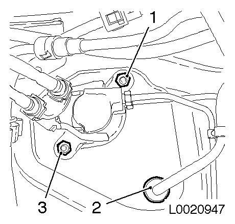
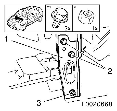
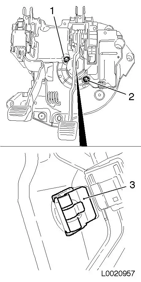
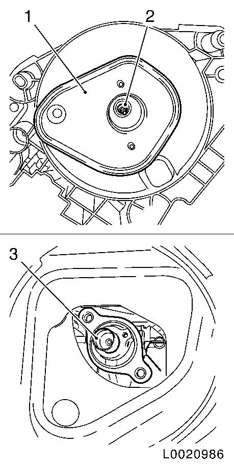
Detach brake master cylinder from brake servo
| • |
Unscrew 2x nut (1), (3)
|
|
| 4. |
Detach vacuum hose (2) from brake servo
|
|
|
| 5. |
Detach lower footwell panelling driver's side
|
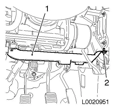
| 6. |
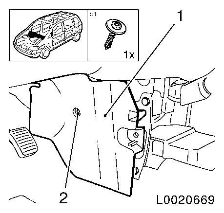
Remove air guide driver's side lower (1)
| • |
Remove expanding rivet (2)
|
|
|
|
| 7. |
Lower inner panelling instrument panel padding - driver's
side
| • |
Open cover flap left and right
|
| • |
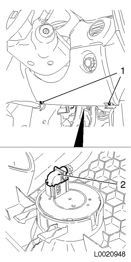
Release and separate wiring harness plug for light switch
centre (2)
|
|
|
|
| 8. |
Remove central console
|
| 9. |
Remove panelling instrument panel padding (1) lower centre -
both sides
|
|
|
| 10. |
Detach fixing brace (1) instrument panel padding - both
sides
|
|
|
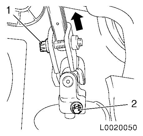
Important: Before pulling the
steering intermediate spindle (1) from the steering pinion or
spindle, move the steering to the straight ahead position and lock
with steering lock.
|
| 11. |
Detach steering intermediate spindle from steering gear
| • |
Unscrew 2x bolt (1), (2)
|
| • |
Push up joint (arrow) and pull steering spindle from steering
gear
|
|
|
|
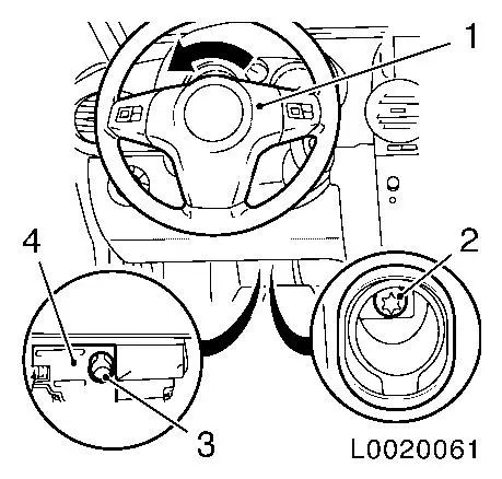
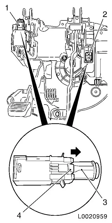
| 12. |
Detach steering intermediate spindle from EPS steering
column
| • |
Twist steering wheel (1) to right in direction of travel by
90°!
|
| • |
Unscrew bolt (2) through assembly opening (3) on EPS control
unit (4)
Note: Diagram shows
LHD. Procedure for RHD is similar.
|
|
|
|
| 13. |
For MT: Detach clutch pedal from clutch master cylinder
|
|
|
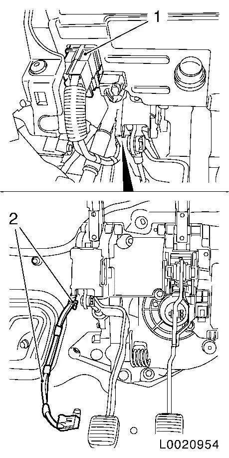
| 14. |
Release and separate 2x wiring harness plug
| • |
Brake light switch (1) and accelerator pedal sensor (2)
|
|
|
|
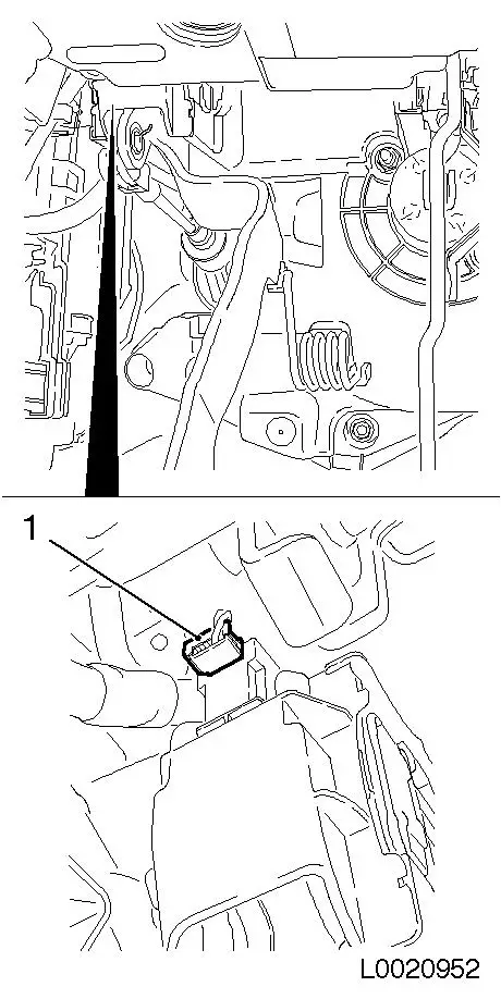
| 15. |
For MT: release and separate wiring harness plug (1) clutch
pedal sensor
|
|
|
| 16. |
Remove accelerator pedal (2)
|
|
|
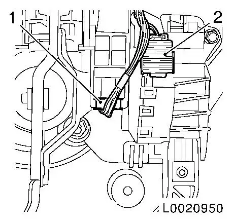
| 17. |
Release and separate wiring harness plug (1) EPS unit
| • |
Unclip wiring harness (2) from pedal mounting
|
|
|
|
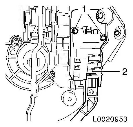
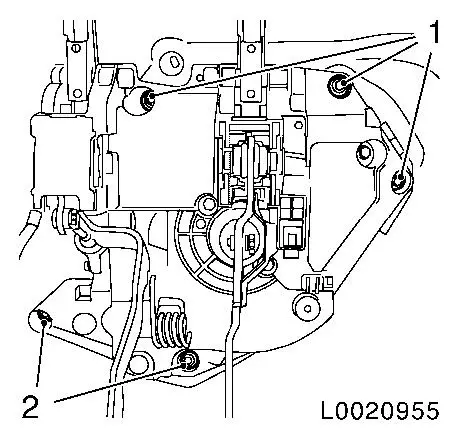
| 18. |
Detach pedal mounting
| • |
Unscrew 5x fastening nut (1), (2)
|
|
|
|
|
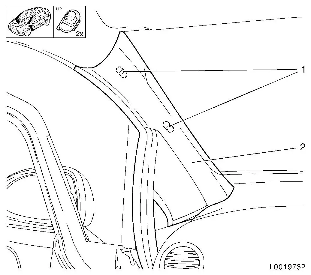
| 19. |
Remove A-pillar panelling (2) - both sides
| • |
Remove A-pillar panelling from guide
|
|
|
| 20. |
Detach instrument panel padding cover top side - both sides
| • |
Unclip and remove from guide
|
|
|
|
|
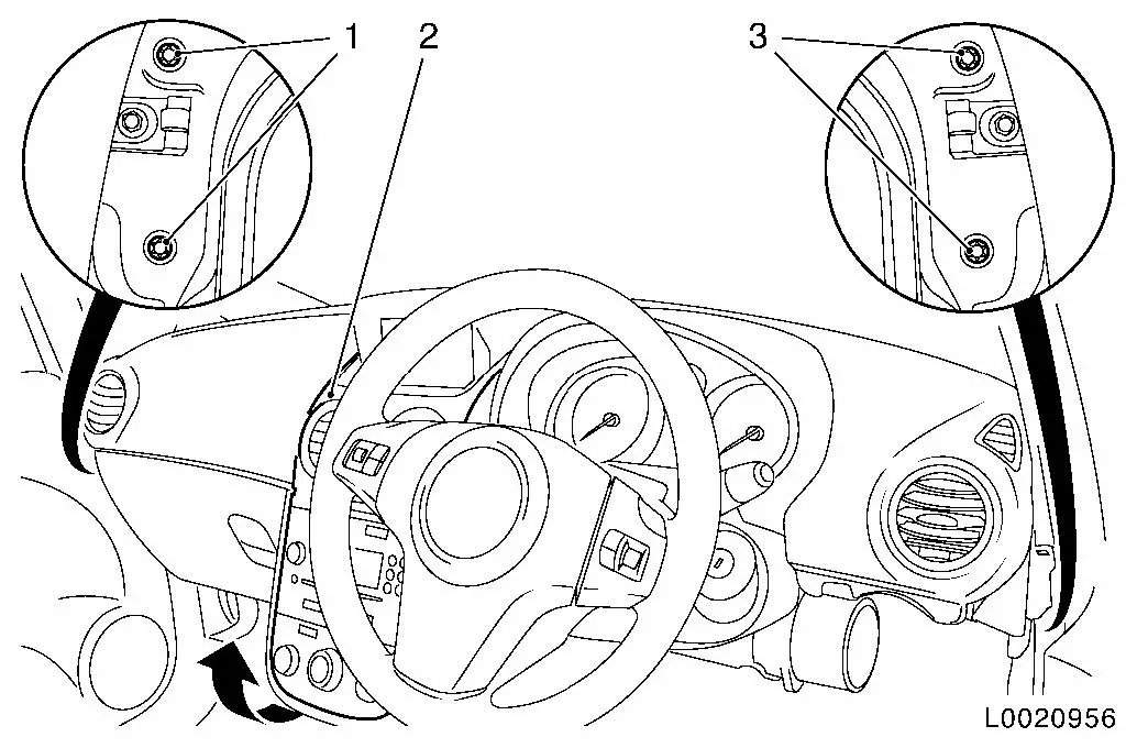
| 21. |
Detach assembly of steering crossmember and instrument panel
padding (2)
| • |
Unscrew 4x bolt (1), (3)
Note: Watch for spacers
at bottom!
|
|
| 22. |
Pull assembly of steering crossmember and instrument panel
padding (2) to rear and swivel up (arrow)
|
| 23. |
Remove pedal mounting in conjunction with brake servo
Note: 2nd person
required to hold assembly of steering crossmember and instrument
panel padding (2). Closing plate drops out!
|
| 24. |
Swivel assembly of steering crossmember and instrument panel
padding (2) back to installation position.
|
|
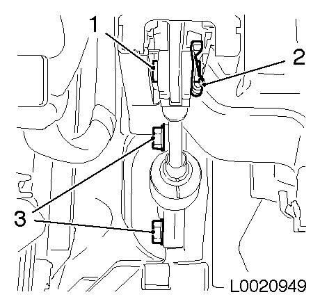
| 25. |
Detach piston rod from brake pedal
| • |
Detach retaining clip (3)
|
|
| 26. |
Detach brake servo from pedal mounting
| • |
Unscrew 2x nut (1), (2)
|
|
|
|
| 27. |
Detach brake light switch (2), and on MT clutch pedal switch
(1)
| • |
Release 2x switch retainer (3) in direction of arrow.
|
| • |
Remove brake light switch (2), and on MT clutch pedal switch
(1)
| – |
Release 4x retaining lug (4)
|
|
|
|
|
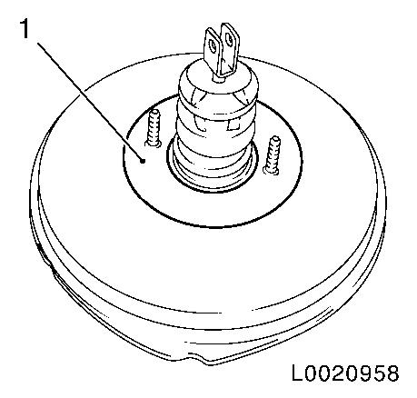
| 28. |
Transfer spacer plate (1) (when replacing brake servo)
| • |
Replace seal front on brake servo
|
|
|
|
| 29. |
Attach brake light switch, and on MT clutch pedal switch
|
| 30. |
Attach brake servo to pedal mounting
|
| 31. |
Attach piston rod to brake pedal
|
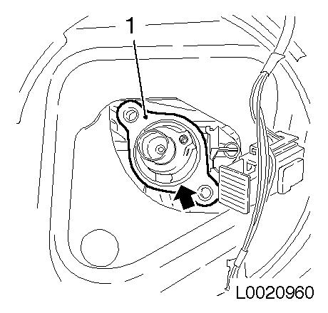
| 32. |
Replace seal (arrow) on brake master cylinder (1)
|
|
|
 Install
| 33. |
Pull assembly of steering crossmember and instrument panel
padding to rear and swivel up
|
| 34. |
Insert pedal mounting in conjunction with brake servo
Note: 2nd person
required to hold assembly of steering crossmember and instrument
panel padding. Fit closing plate (2)! Ensure that the pushrods of
the brake servo (1) sit in the piston rod (3) of the brake master
cylinder.
|
|
|
| 35. |
Place assembly of steering crossmember and instrument panel
padding in installation position
Note: Use a second
person
|
| 36. |
Attach assembly of steering crossmember and instrument panel
padding
| • |
Insert assembly of steering crossmember and instrument panel
padding
Note: 2nd person
required
|
| • |
Tighten 2x bolts right ( 20 Nm
)
|
| • |
Tighten 2x bolts left ( 20 Nm
)
|
|
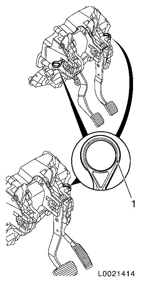
| 37. |
Release pedal set
| • |
Remove locking pin (1)
Note: Top view shows
pedal mounting for MT. Bottom view shows pedal mounting for AT.
|
|
|
|
| 38. |
Attach pedal mounting
|
| 39. |
Attach instrument panel padding cover top side - both sides
| • |
Insert in guide and clip in
|
|
| 40. |
Install A-pillar panelling - both sides
| • |
Insert A-pillar panelling in guide - both sides
|
| • |
Clip in 2x clip - both sides
|
|
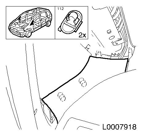
| 41. |
Attach quarterlight panelling - left
|
| 42. |
Attach wiring harness EPS unit
| • |
Connect and lock wiring harness plug
|
|
| 43. |
Install accelerator pedal
| • |
Connect and lock wiring harness plug
|
| • |
Connect wiring harness plug for brake light switch
|
|
| 44. |
On MT: Connect wiring harness plug for clutch switch
|
| 45. |
On MT: Attach clutch master cylinder
| • |
Attach master cylinder to pedal mounting
|
| • |
On MT: Attach master cylinder to clutch pedal
|
|
| 46. |
Push upper universal joint of steering intermediate spindle
onto steering column
Note: The square of the
upper universal joint only aligns in one position.
| • |
Tighten new bolt at top 24 Nm +
60°
|
|
| 47. |
Fit upper clamping bolt of steering intermediate spindle on
steering spindle with locking compound and tighten
|
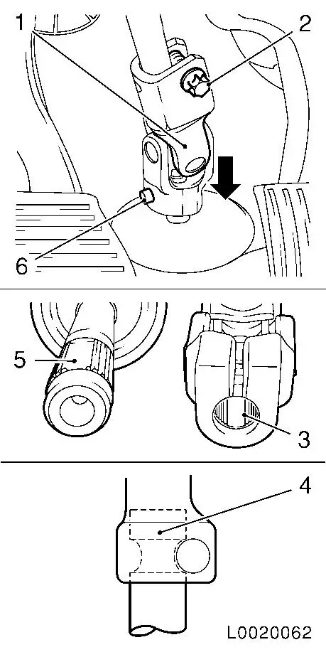
| 48. |
Attach lower universal joint (1)
| • |
Push onto steering spindle (arrow)
Note: The recess (3) in
the fine toothing in the lower universal joint must align precisely
with the recess (5) in the fine toothing on the steering pinion.
The bore in lower universal joint (1) must align with the groove on
the steering pinion (4).
|
| • |
Fit bolt (6) with locking compound and tighten 55 Nm
|
| • |
Fit bolt (2) with locking compound and tighten 40 Nm
|
|
|
|
| 49. |
Attach fixing brace instrument panel padding - both sides
|
| 50. |
Attach panelling instrument panel padding lower centre - both
sides
|
| 51. |
Install central console
|
| 53. |
Attach brake master cylinder
|
| 54. |
Program volatile memories
|
| 55. |
Bleed brake system and check for leaks 
|
|
