|
Cup Tappets, Replace
Important: When
working on the fuel system maintaining cleanliness is essential,
otherwise the smallest particles of dirt may result in engine
operating faults or faults in the fuel system. Open fuel
connections must be sealed off with suitable sealing plugs from the
Opel parts catalogue. Sealing plugs are designed for single use
only.
 Remove Remove
| 2. |
Disconnect battery
| • |
Detach negative clamp from earth terminal
|
|
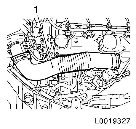
| 4. |
Remove air intake pipe (1) together with air mass flow
meter
| • |
Disconnect wiring harness plug of air-flow meter
|
|
|
|
| 5. |
Place collecting basin underneath.
|
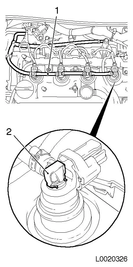
| 6. |
Detach fuel return line (1) from injector
| • |
4x from injector
| – |
Release retaining clamps (2)
|
|
| • |
Seal off line and connections with sealing caps
|
|
|
|
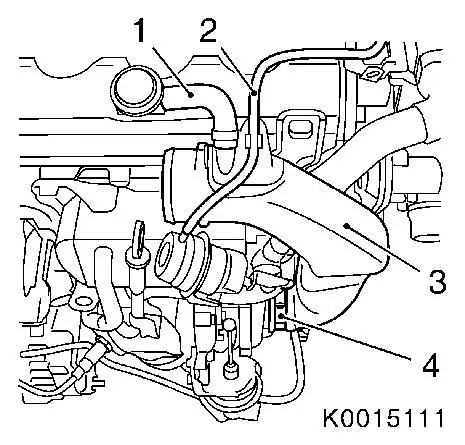
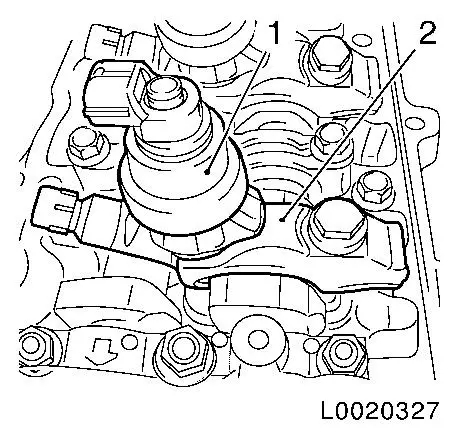
| 7. |
Remove charge air pipe (3)
| • |
Detach engine vent hose (1) from camshaft housing cover
|
| • |
Unclip hose for wastegate unit of exhaust gas recirculation
cooler bypass valve (2)
|
|
|
|
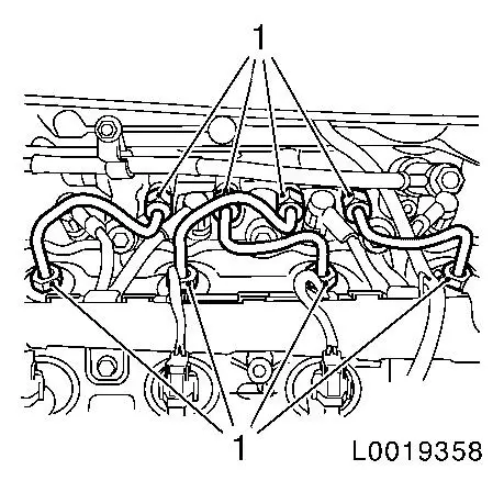
| 8. |
Remove 4x high-pressure lines
| • |
Unscrew 8x lock nut (1)
|
| • |
Seal off connections on pressure chamber with suitable sealing
caps
|
| • |
Seal off connections on injector with EN-48559
|
|
|
|
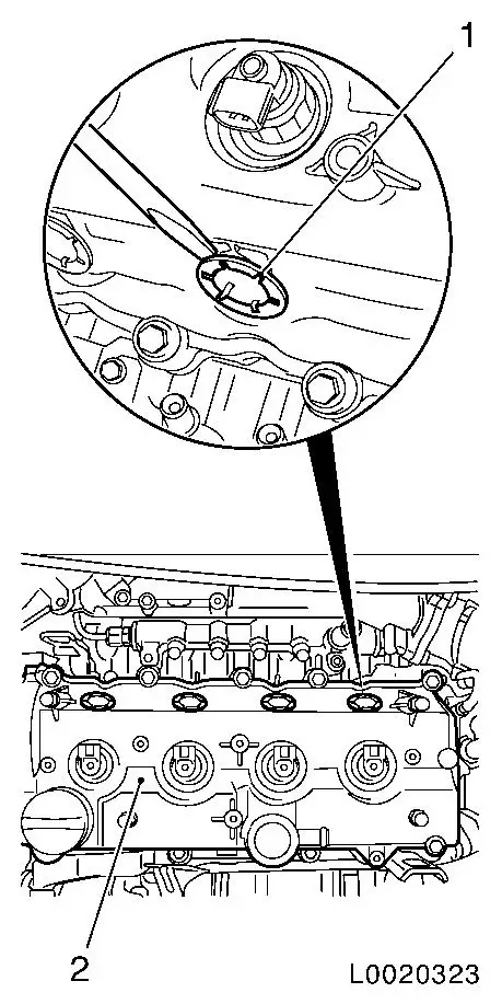
| 9. |
Remove camshaft housing cover (2)
| • |
Remove 4x injector seals (1)
|
|
|
|
| 10. |
Remove 4x injector (1)
|
|
|
| 14. |
Lower vehicle by its full height
|
| 15. |
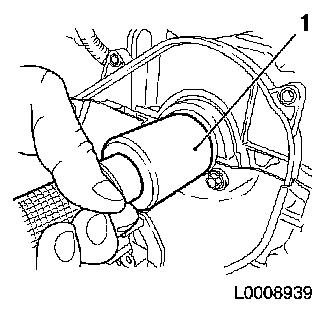
Remove camshaft sprocket
| • |
Remove TDC fixing bolt (1)
| – |
Unscrew bolt
Note: Counterhold it
with KM-6347 (3) together with KM-956-1 (2)
|
|
|
|
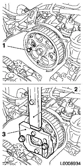
|
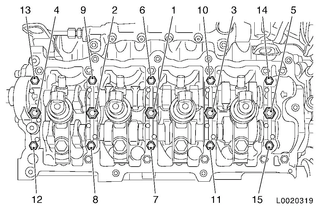
| 16. |
Remove camshaft bearing cap 5 (1)
|
|
|
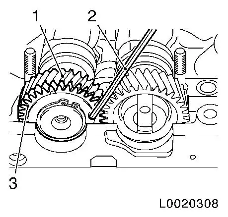
| 17. |
Lock exhaust camshaft gear wheels
| • |
Lock balancer gear wheel, exhaust camshaft (3), with balancer
camshaft gear wheel (1) with KM-6092-10
(2) so that it cannot twist
|
|
|
|
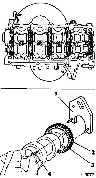
| 18. |
Remove 2x camshafts
Note: Note marking
before dismantling camshaft bearing cap
| • |
Release the camshaft bearing caps in the order specified,
working in a spiral pattern in stages of 1/2 to 1 turn
Note: When replacing
the exhaust camshaft, the balancer gear wheel (2) must be
pre-tensioned with KM-6092 (1) and
connected to the gear wheel of the exhaust camshaft (3) with fixing
pin KM-6092-10 (4)
|
|
|
|
| 19. |
Remove 16x cup tappets with KM-845
|
 Install
| 20. |
Install 16x cup tappets with KM-845
Note: Observe correct
assignment
|
| 21. |
Remove camshaft seal ring (1)
|
|
|
| 22. |
Clean sealing surface
| • |
Camshaft housing, camshaft bearing caps
|
|
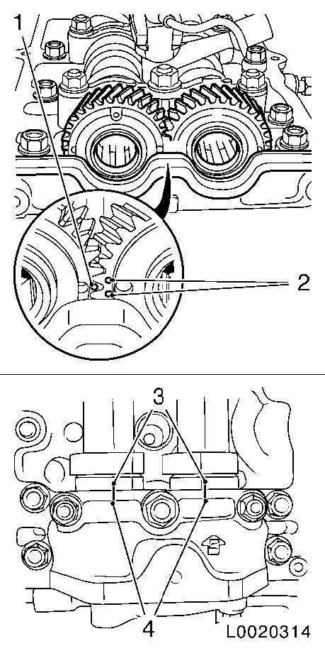
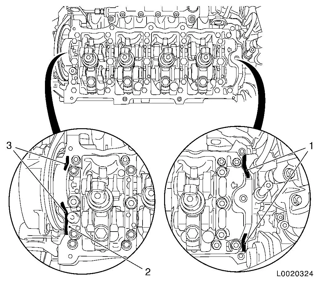
Important: When installing the
camshafts, ensure that the mark (1) on the exhaust camshaft gear
wheel is between the two marks (2) on the intake camshaft gear
wheel and that the marks on the camshaft bearing cap (4) are in
line with the two marks on the camshafts (3)
|
| 23. |
Insert 2x camshafts
| • |
Insert camshaft in camshaft housing
Note: Coat bearing
positions with engine oil
|
|
|
|
|
| 24. |
Tighten 2x camshafts
Note: Coat bearing
positions with engine oil
| • |
Attach camshaft bearing caps 1 - 4 to camshaft housing
Note: Arrows on bearing
caps point towards engine timing side
|
| • |
Attach camshaft bearing cap 5
| – |
Remove KM-6092-10 from exhaust
camshaft gear wheel
|
|
| • |
Tighten the camshaft bearing caps in the order specified (1 -
15) in stages of 1/2 to 1 turn
|
|
|
| 25. |
Insert camshaft seal ring
| • |
Drive in flush using KM-656 (1)
|
|
|
|
| 26. |
Check valve clearances and adjust if necessary 
|
| 27. |
Install camshaft sprocket
Note: Camshaft journal
(2) must engage in the bore (1) in the camshaft sprocket
| • |
Tighten bolt 111 Nm
| – |
Counterhold it with KM-6347 together
with KM-956-1
|
|
Important: Do not damage
increment disc
|
| • |
Screw in TDC fixing bolt
|
|
|
|
| 28. |
Raise vehicle by its full height
|
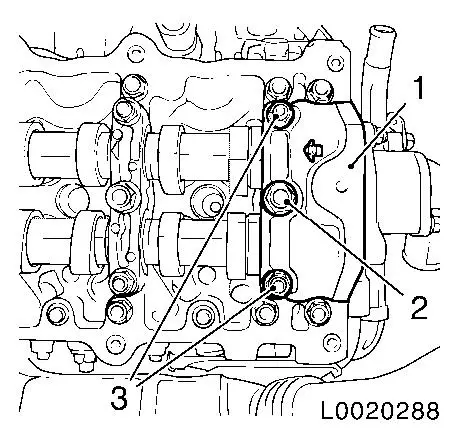
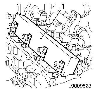
| 31. |
Install 4x injector
Note: Replace 4x
injector seals
| • |
Install 4x brackets
| – |
Align injectors with EN-48560 (1)
|
| – |
Tighten 4x bolt in three stages
|
|
|
|
|
| 32. |
Clean sealing surface
|
|
Important: Oil return bore (2)
may not be covered with adhesive sealing compound
|
| 33. |
Apply sealing compound
Note: Select a suitable
sealing compound from the replacement parts catalogue
| • |
Apply adhesive sealing compound to sealing surfaces (1) and
(3)
|
|
|
| 34. |
Install camshaft housing cover
| • |
Tighten 10x bolts 10 Nm
|
| • |
Install 4x injector seals
|
|
| 35. |
Install 4 high-pressure lines
Note: Attach first to
injector, then to pressure chamber
| • |
Detach 4x sealing caps from pressure chamber
|
| • |
Detach 4x EN-48559 from injector
|
| • |
Tighten 8x union nut 25 Nm
|
|
| 36. |
Fit charge air pipe
| • |
Attach engine vent hose to camshaft housing cover
|
|
| 37. |
Attach fuel return line to injector
| • |
Fasten 4x retaining clamps
|
|
| 38. |
Install air intake pipe together with air mass flow meter
| • |
Connect mass air flow meter wiring harness plug
|
|
| 40. |
Connect battery
| • |
Attach earth clamp to earth terminal
|
|
| 41. |
Program volatile memories
|
|
