|
Installation height of valves, check
Special service tools required:
Caliper gauges, KM-419 (OHC I), KM-512 (OHC II), measuring
bridge KM-301, dial gauge MKM-571-B
Note: The
engine-specific values can be found in the corresponding "Technical
Data".
|
Preconditions:
Cylinder head sealing surface and valve heads are cleaned.
 Measure
The installation height of the valves can be checked from both
the underside and from the upper side of the cylinder head.
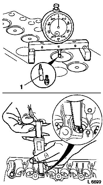
 Assemble
If the valve indentation cannot be determined, the extension
provided (1) should be inserted between dial gauge shaft and
probe.
|
|
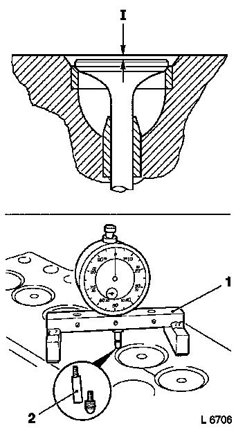
Measurement from underside of cylinder head (valve
indentation)
|
Measure
Valve indentation (I) can be determined using measuring bridge
KM-301 and dial gauge MKM-571-B.
 Clean Clean
Position Measuring bridge KM-301 (1) on cleaned sealing surface,
insert Dial gauge MKM-571-B under pretension, fasten and adjust
dial to Zero.
Assemble
If the valve indentation cannot be determined, the extension
provided (2) should be inserted between dial gauge shaft and
probe.
|
|
|
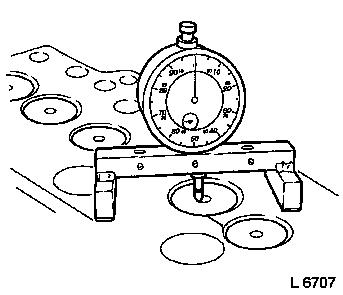
 Inspect
Position dial gauge MKM-571-B with measuring bridge KM-301 at
valve head and measure indentation of valve.
The specified valve indentation and the dimensions can be found
in the "Technical Data".
|
|
|
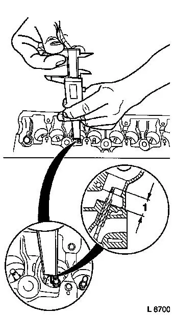
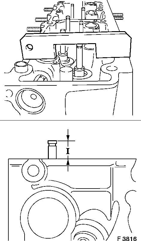
Inspect
The installation height (1) of the valves should be measured
from the upper side of the cylinder head using the depth gauge of a
caliper gauge. The measurement is taken from the valve shaft end to
the cylinder head.
The specified valve projection and the dimensions can be found
in the "Technical Data".
|
|
|
Inspect
In the OHC I engines, measurements are made using KM-419 and in
OHC II engines using KM-512.
 Install
If dimension (I) is exceeded, insert new valve and check valve
stem projection again. If the valve stem projection is too great
despite replacement of the valve, the cylinder head must be
replaced.
Note: In the X 15 DT,
X 17 DT engines the valve seat rings can also be replaced. See
"Valve seat rings, replace (X 15 DT, X 17 DT)".
The specified valve projection and the dimensions can be found
in the "Technical Data".
|
|
|
