|
Fit and remove engine bridge to engine
Note: The following
overview shows all special tools required for the procedure!
|
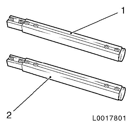
EN-47649 (1) in connection with EN-47649-100 (2)
|
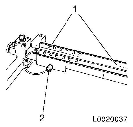
Engine bridge (1) with special feet (2)
|
|
Hold/lower/raise engine
|
|
|
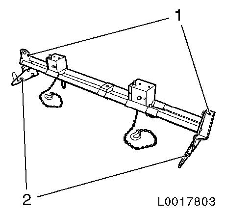
|
|
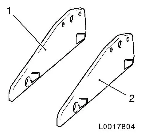
EN-47649-100 (1), (2)
|
2x special feet to convert engine bridge MKM-883-1-A
|
|
|
|
EN-47650-150 (1)
|
2x adapter for fitting carrier frame EN-47650 to Corsa-D
|
|
|
|
|
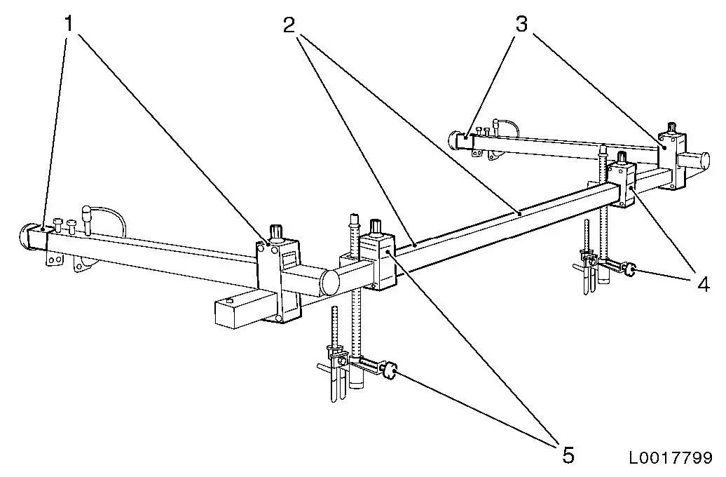
EN-47650
|
Carrier frame - engine bridge (assembly)
|
|
EN-47650-010 (2)
|
Crossbar
|
|
EN-47650-020 (1), (3)
|
2x longitudinal bar, 2x clamping support
|
|
EN-47650-040 (4), (5)
|
2x height spindle
|
|
|
EN-47650-030 (1), (2) not required on
Corsa-D
|
2x extension to longitudinal bar EN-47650-020
|
|
|
|
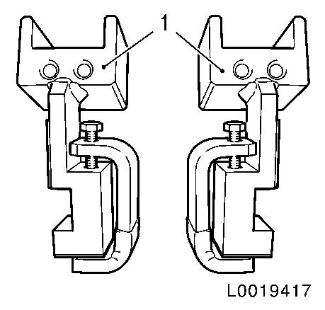
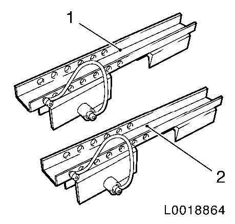
EN-47650-50 (1), (2)
|
Holder rail for engine bridge EN-47649
|
|
|
 Install
| 1. |
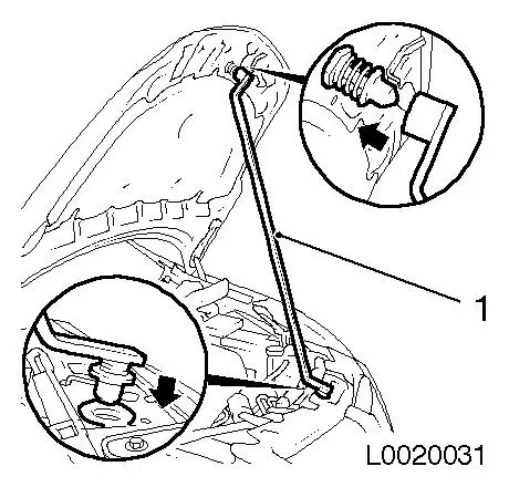
Support bonnet with EN-48375 (1)
| • |
Insert EN-48375 (1) at bottom in hole
for bonnet catch
|
| • |
Place EN-48375 (1) at top on engine
catch bolt
|
|
|
|
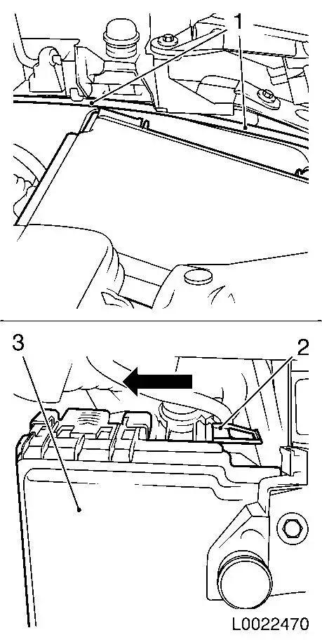
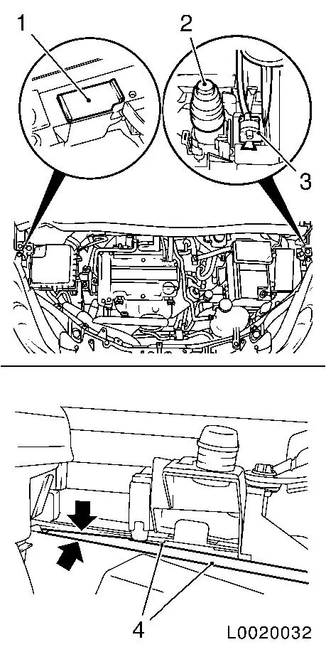
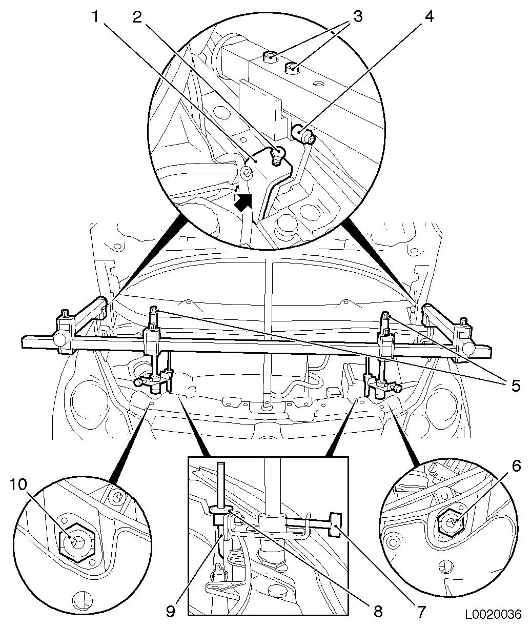
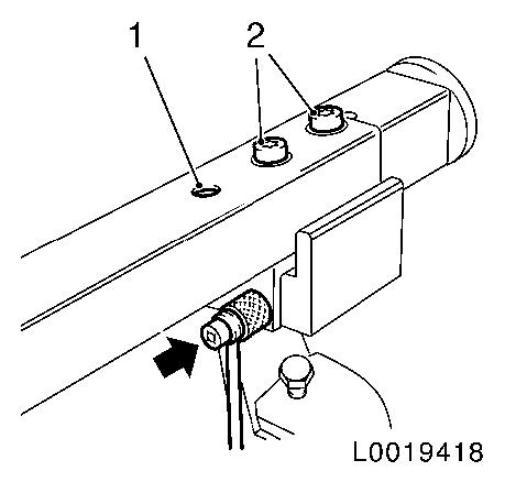
Important: From MY 2008:
|
| 2. |
When installing the engine bridge, the revised engine
compartment electronics module (3) may in some circumstances make
it difficult to release the Bowden cable (1). To prevent damaging
the Bowden cable, it may be necessary to unclip the engine
compartment electronics module on one side (2) and carefully push
it to one side (arrow). The Bowden cable can then be placed to one
side without damaging it.
|
|
|
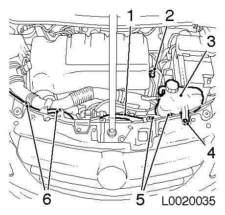
| 3. |
If fitted: pull alarm system switch (2) from guide and lay
aside
|
| 4. |
Remove bonnet support holder (3)
Note: Release retaining
lug with screwdriver. See diagram.
Important: Do not kink bonnet
release cable (4)!
|
| • |
Expose bonnet release cable (4)
|
| • |
Remove service flap right (1)
|
| • |
Clean grease and dirt from exposed service openings (arrows) on
both sides, on top and bottom
|
|
|
|
|
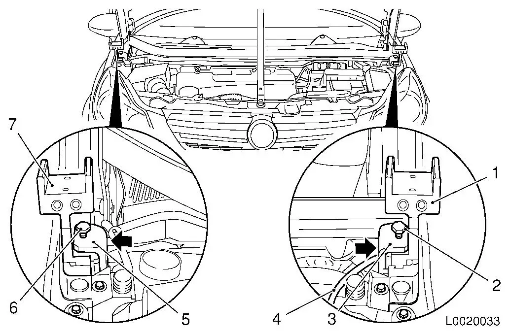
Important: Attach wing
protectors! Risk of paint damage!
|
| 5. |
Attach 2x adapter EN-47650-150 (1)
and EN-47650-150 (6) at exposed service
opening on both sides
Note: Ensure that
adapter EN-47650-150 (1) and EN-47650-150 (6) lie completely on the outer wing
edge. Ensure that adapter EN-47650-150
(6) does not clamp the bonnet release cable (7).
| • |
Screw in 2x bolt (2), (5)
Note: Do not tighten
bolts! While screwing in, press retaining bracket (3), (4) on
adapter EN-47650-150 (1) or EN-47650-150 (6) without play (arrows)
|
|
|
|
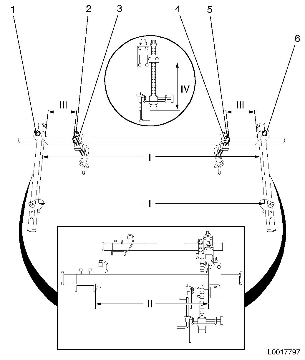
| 6. |
Pre-set carrier frame EN-47650 to
correct dimensions
Note: Pre-set special
tool assembly to table outside the vehicle!
|
Dimension I
|
1330 mm
|
|
Dimension II
|
435 mm
|
|
Dimension III
|
245 mm
|
|
Dimension IV
|
165 mm
|
Note: The magnifying
glass in the diagram shows a side view of EN-47650
| • |
Attach 2x clamping blocks EN-47650-020
| – |
Tighten 2x hex heads (1), (6)
|
|
| • |
Set 2x height spindles EN-47650-040
| – |
Tighten 2x hex heads (2), (5)
|
| – |
Adjust 2x at hex heads (3), (4)
|
|
|
|
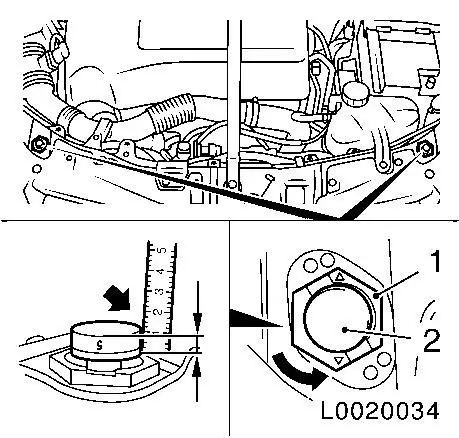
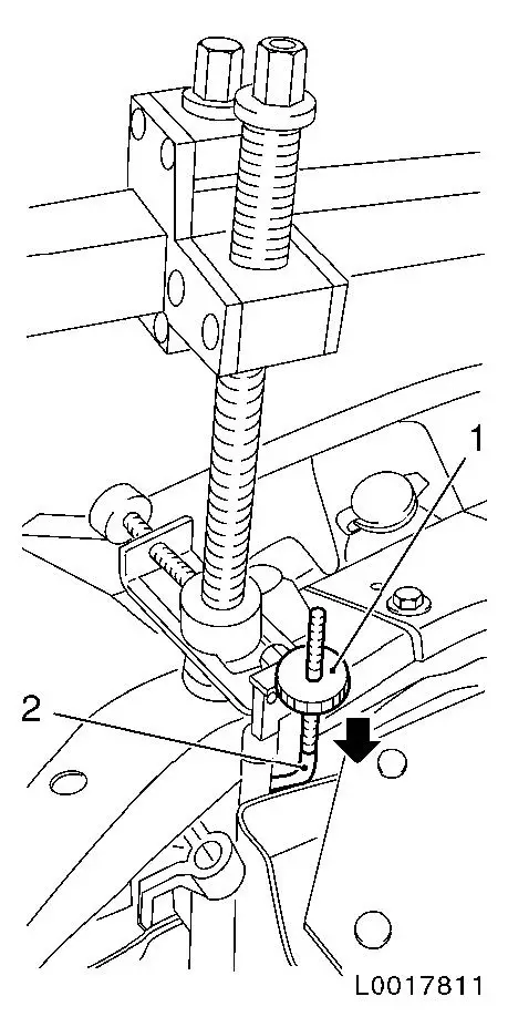
| 7. |
Remove 2x bonnet buffers (2) left and right
Note: Before removal,
measure installation height (arrow) of bonnet buffers left and
right, and record.
| • |
Twist catch (1) through 180°
| – |
Remove 2x bonnet buffers (2)
|
|
|
|
|
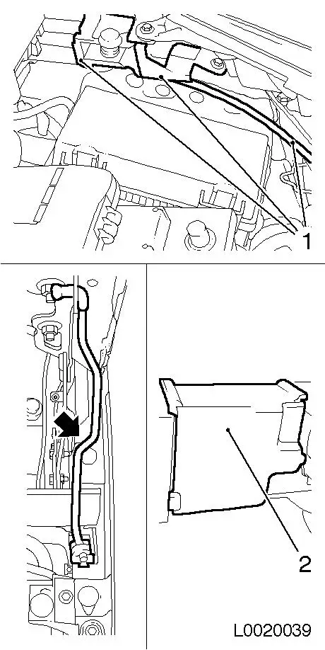
| 8. |
Remove coolant expansion tank (3) and lay aside
| • |
Unclip hose (2) from upper engine bay cover
|
|
| 9. |
Detach wiring harness (1) from top front
|
|
|
|
| 10. |
Fit pre-assembled carrier frame EN-47650
Note: 2nd person
required!
| • |
Fit 2x pin (4) in bores on both sides
Note: Ensure that the
rubber feet of the height spindle sit at the marked points on the
installation positions (6), (10) of the bonnet.
|
| • |
Attach 2x adapter EN-47650-150 both
sides
|
| • |
Tighten 2 bolts (2)
Note: During
tightening, the retaining brackets (1) must be pressed play-free on
the adapters EN-47650-150 (arrow)
|
| • |
If necessary: adjust position of rubber feet at knurled wheel
(7) on both sides
|
|
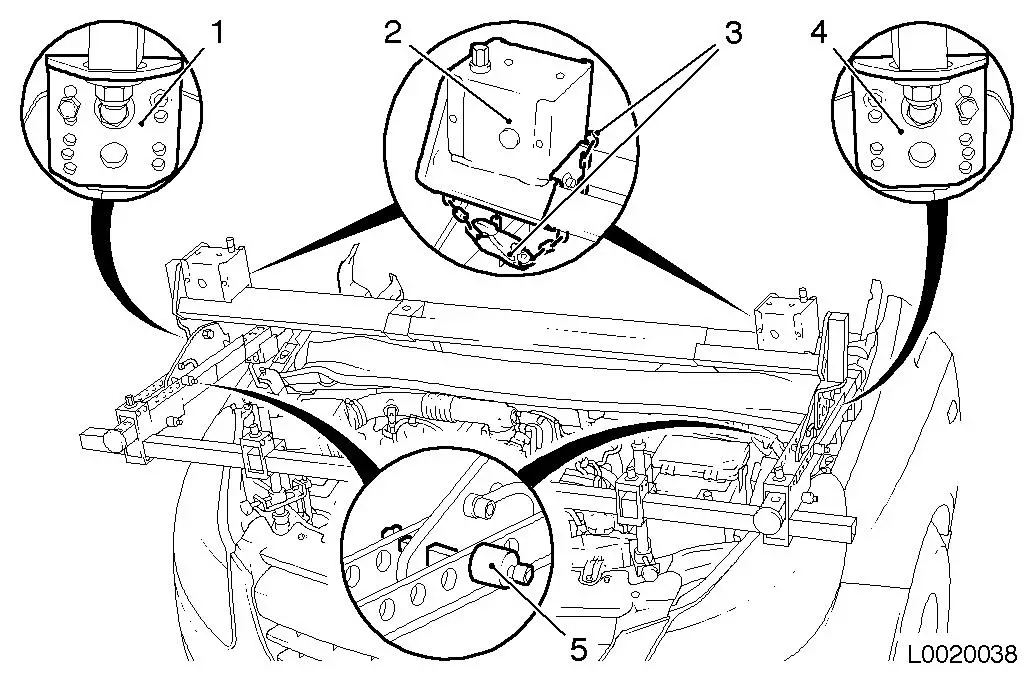
| 11. |
Fit carrier frame EN-47650
| • |
Tighten 4x bolt (3) both sides
|
| • |
Secure height spindle EN-47650-040 at
top front
Note: If necessary:
adjust height of height spindle EN-47650-040 at both sides at hex head (5)
| – |
Position 2x retaining hooks (9) under top front
|
| – |
Twist 2x holders to position shown at knurled wheel (8) on both
sides
|
|
|
|
| 12. |
Place holder rails EN-47650-50 (1) on
carrier frame EN-47650 at both sides
| • |
Secure with pins (2) at both sides
Note: Check for correct
position!
|
|
|
|
|
| 13. |
Attach engine bridge EN-47649 (2)
|
Warning: Only fit EN-47649 in secure state! Wind retaining chains (3)
about chain box (2) and engine bridge foot EN-47647-100 and tighten chains at hex head on chain
box.
|
| 14. |
Insert engine bridge EN-47649 (2) in
holder rail EN-47650-50
Note: Insert engine
bridge EN-47649 and position evenly!
Note: 2nd person
required. Engine bridge must be perpendicular. Adjust at adjustment
plates (1), (4)
| • |
Secure EN-47649 with pins (5) both
sides
Note: Check for even
positioning of EN-47649
|
|
|
 Remove Remove
Warning: Only remove EN-47649 in secure state! Wind retaining chains about
chain box and engine bridge foot and tighten chains at hex head on
chain box.
|
| 15. |
Remove engine bridge EN-47649
| • |
Remove 2x securing pins and release engine bridge foot EN-47649-100
|
| • |
Raise engine bridge EN-47649 from
holder rail EN-47650-50
Note: 2nd person
required!
|
| • |
Secure retaining chains of EN-47649
on both sides
|
|
| 16. |
Remove holder rail EN-47650-50 from
carrier frame EN-47650 on both sides
|
| 17. |
Remove carrier frame EN-47650
| • |
Release 2x safety pins (arrow) on both sides and place in hole
(1)
|
|
|
|
| 18. |
Remove carrier frame EN-47650
(continued)
| • |
Remove 2x retaining hooks (2) for height spindle EN-47650-040
|
| • |
Turn up 2x knurled screws (1)
|
| • |
Press 2x retaining hooks (2) down (arrow)
|
| • |
Fold out 2x retaining hooks from top front
|
|
Important: Watch for paint
damage!
|
| 19. |
Remove carrier frame EN-47650
Note: 2nd person
required!
|
|
|
| 20. |
Remove 2x adapter EN-47650-150
|
| 21. |
Lay bonnet release cable (1)
Note: Check for correct
installation position!
| • |
From MY 2008:
Clip in engine compartment electronics module
|
| • |
Fit bonnet support (arrow)
Note: Check for correct
installation position!
|
| • |
Where fitted: clip in alarm system switch
|
| • |
Install service flap right (2)
Note: Check for correct
installation position!
|
| • |
Remove bonnet support EN-48375
|
|
|
|
| 22. |
Attach wiring harness to top front
|
| 23. |
Fit coolant expansion tank
|
| 24. |
Adjust bonnet
| • |
Insert 2x bonnet buffers to dimensions previously noted
| – |
Twist catch clockwise through 180°
|
| – |
Close bonnet and check for even lines to wings
|
| – |
If necessary: readjust bonnet buffers
|
|
|
|
