|
Crankshaft drive bearing
 Remove Remove
| 2. |
Remove manual transmission from engine 
|
| 4. |
Detach thrust plate and clutch disk
|
|
|
| 6. |
Attach engine to suitable engine overhaul stand
| • |
Attach KM-2358 to 3x engine transport
shackle
|
| • |
Raise using engine crane
|
| • |
Attach engine to engine overhaul stand
|
| • |
Detach KM-2358 from 3x engine
transport shackle
|
|
| 7. |
Drain engine oil
| • |
Place collecting basin underneath.
|
| • |
Remove oil filter housing cover
|
| • |
Remove oil filter element
|
|
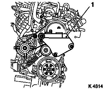
| 8. |
Remove engine bracket right (1)
|
| 9. |
Screw in oil drain bolt
|
|
|
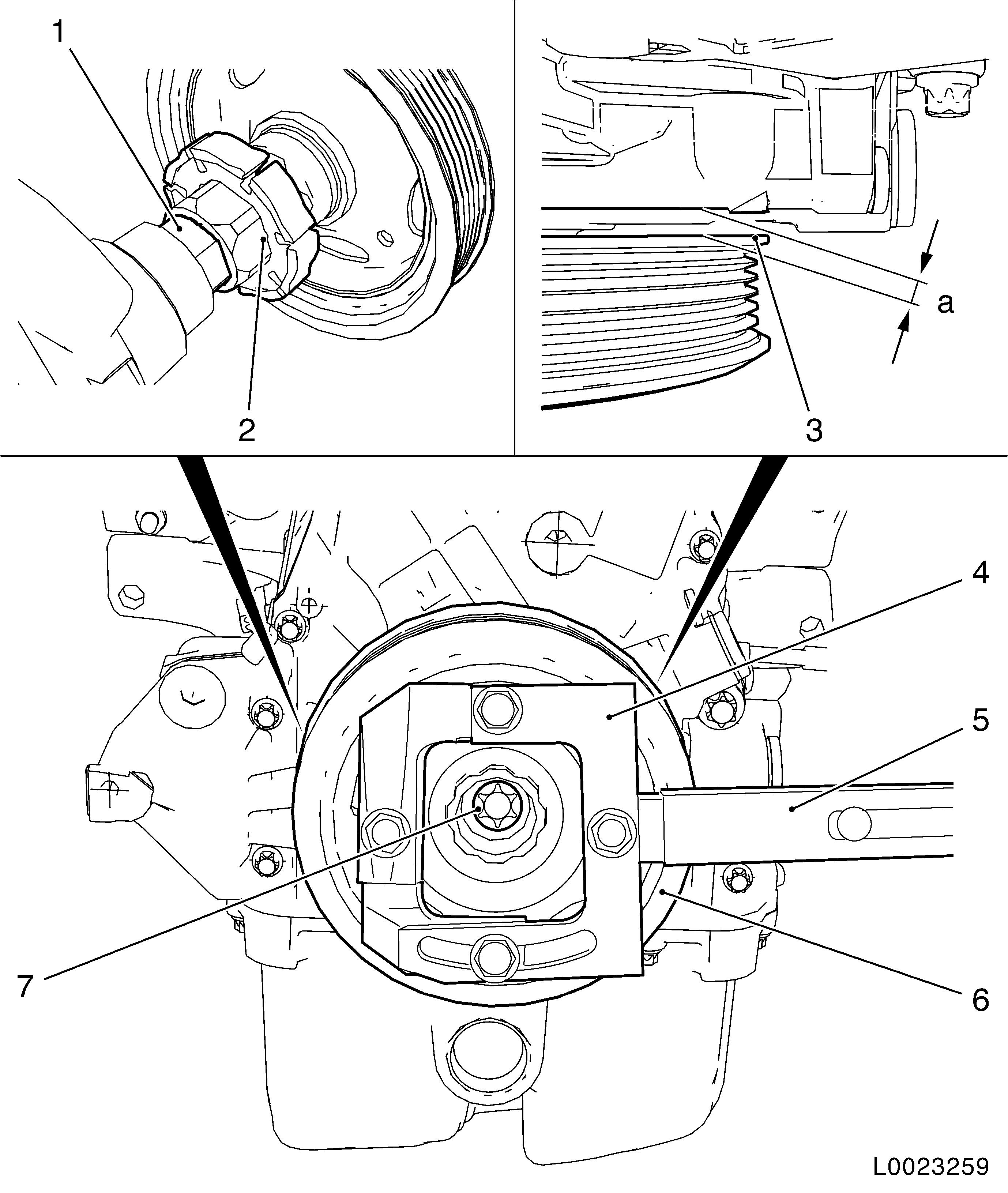
| 10. |
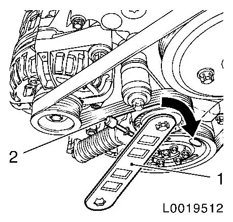
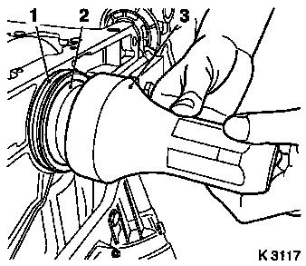
Detach ribbed V-belt
| • |
Mark direction of rotation
|
| • |
Tension the ribbed V-belt tensioner using KM-6131 (1) in the direction of the arrow
|
| • |
Release ribbed V-belt tensioner
|
|
|
|
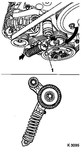
| 11. |
Remove ribbed V-belt tensioner
| • |
Unscrew 2 bolts (arrows)
|
| • |
Remove ribbed V-belt tensioner
|
|
|
|
| 12. |
Detach coolant pump ribbed V-belt pulley
| • |
Unscrew 3x bolts
Note: Counterhold with
open-end wrench
|
|
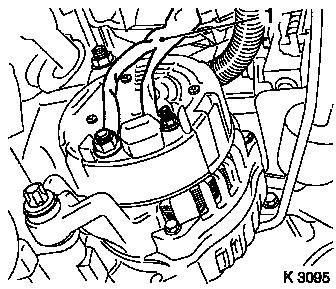
| 13. |
Detach alternator
| • |
Detach alternator wiring harness (1)
|
| • |
Detach 2x bolted connections
|
|
|
|
| 14. |
Detach 3x coolant hoses from coolant pump
|
| 15. |
Unclip engine management wiring harness from cylinder head
cover
| • |
Disconnect 3 wiring harness plugs
| – |
Camshaft sensor, coolant temperature sensor, oil pressure
sensor
|
|
|
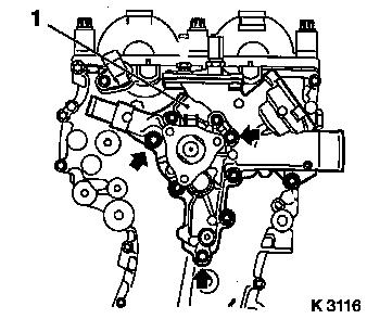
| 16. |
Detach coolant pump (1) together with thermostat housing
Note: When removing
guide sleeves, please note
| • |
Place collecting basin underneath.
|
| • |
Unscrew 9x bolts
Note: Note differing
bolt lengths (arrows = short bolts)
|
|
|
|
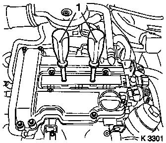
| 17. |
Detach ignition module
| • |
Detach ignition module cover
|
| • |
Disconnect ignition module wiring harness plug
|
| • |
Pull out using KM-6009 (1)
Note: Do not tilt
|
|
|
|
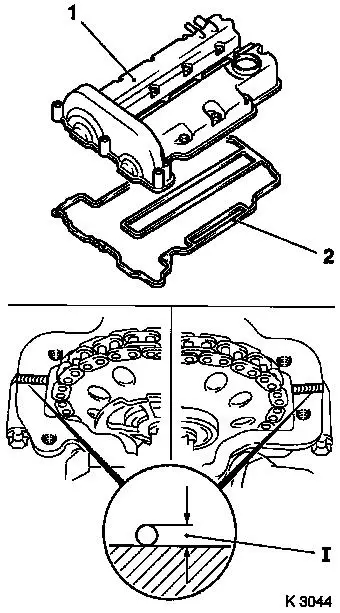
| 18. |
Remove cylinder head cover
| • |
Detach 2 engine vent hoses
|
|
|
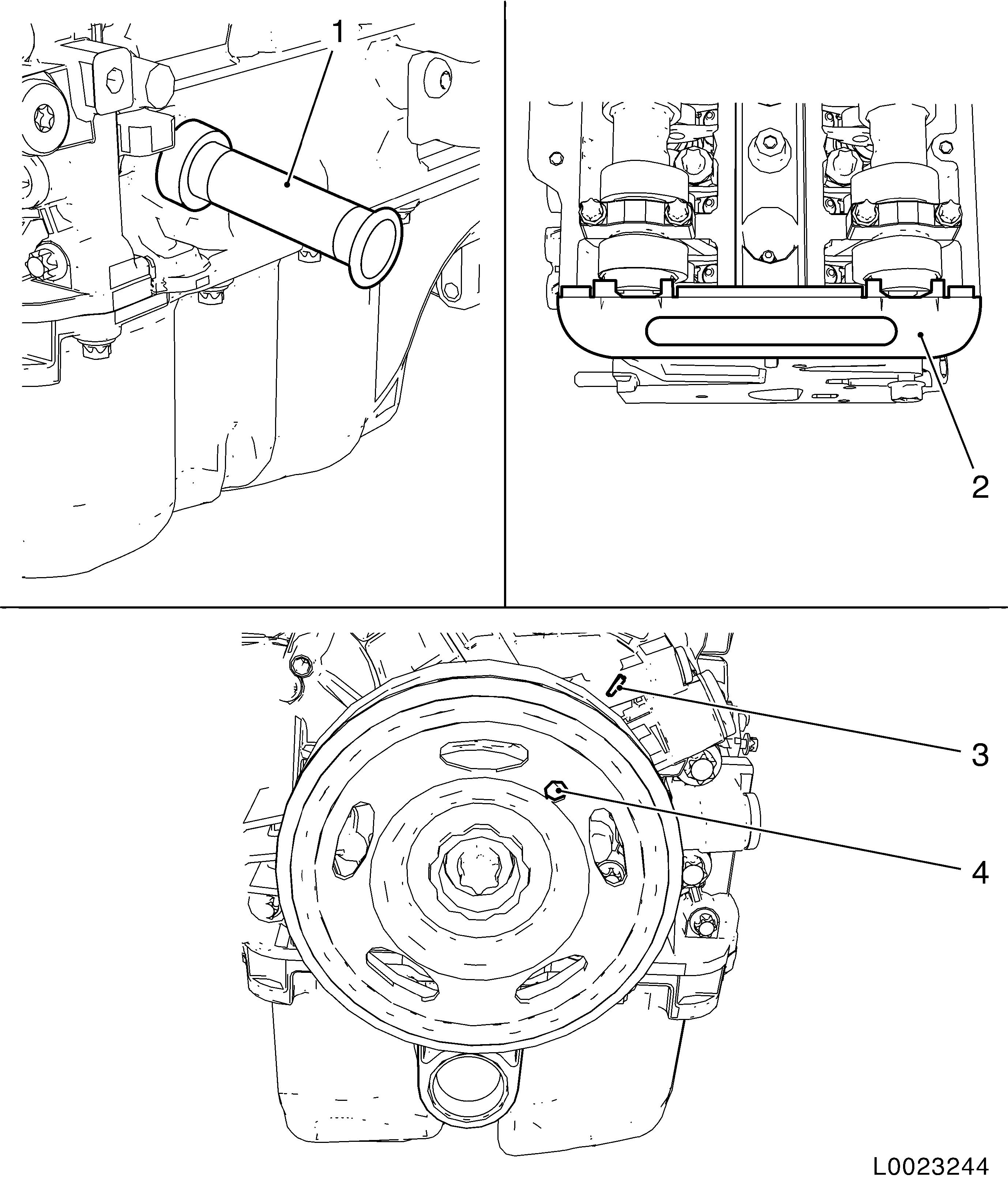
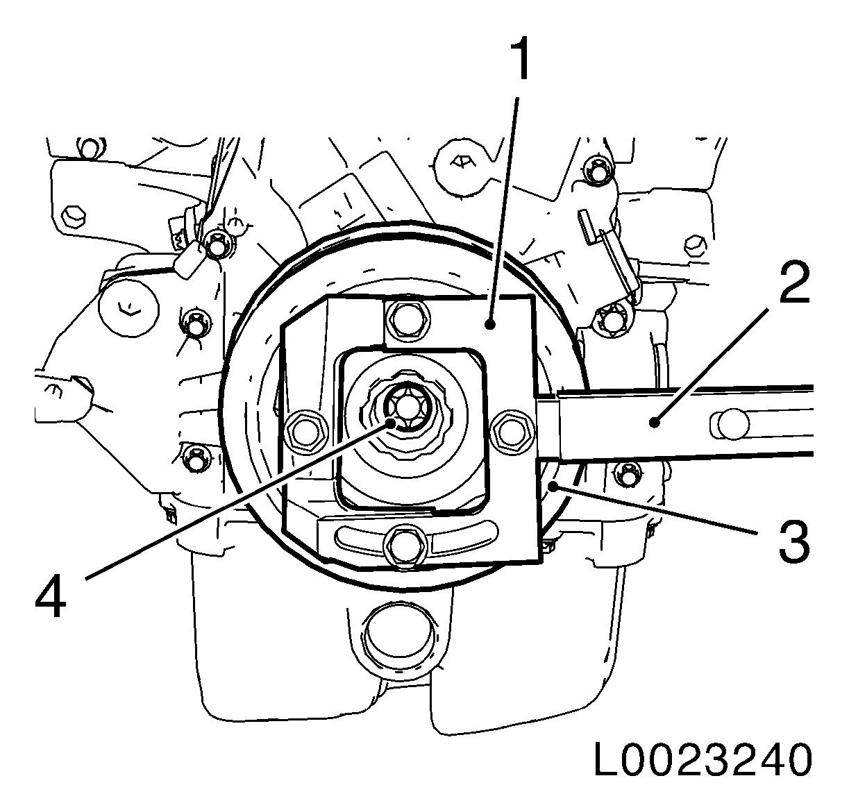
| 19. |
Set engine to TDC of combustion stroke of cylinder 1
| • |
Unscrew crankshaft closure bolt
|
| • |
Rotate crankshaft in direction of engine rotation to the
marking (4) on the torsional vibration damper and align with
marking (3) on timing case
|
Important: It must be possible to
insert EN-953 smoothly and without major
effort into the camshaft grooves.
|
| • |
Lock camshafts with EN-953 (2)
|
Important: It must be possible to
insert KM-952 smoothly and without major
effort into the crankshaft recess.
|
| • |
Fix crankshaft with KM-952 (1)
|
|
|
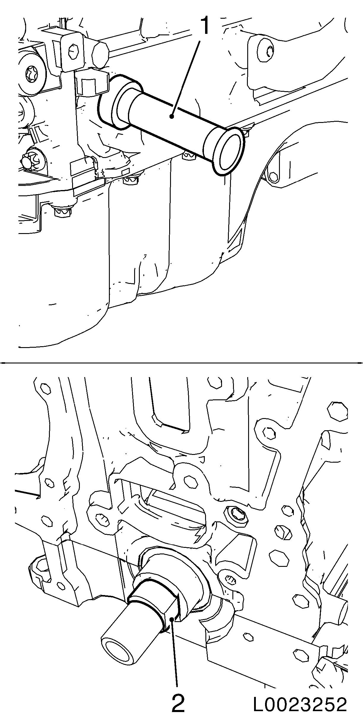
| 20. |
Detach torsional vibration damper (3)
| • |
Counterhold it with EN-49979 (1)
together with KM-956-1 (2)
|
|
|
|
| 21. |
Rotate engine on engine overhaul stand through 180°
|
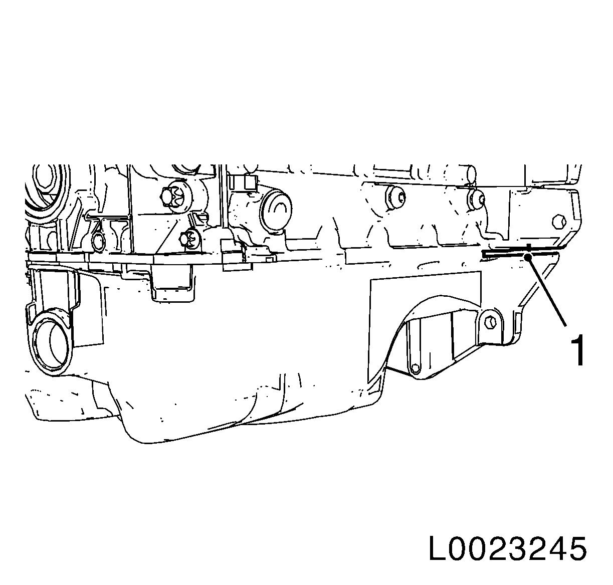
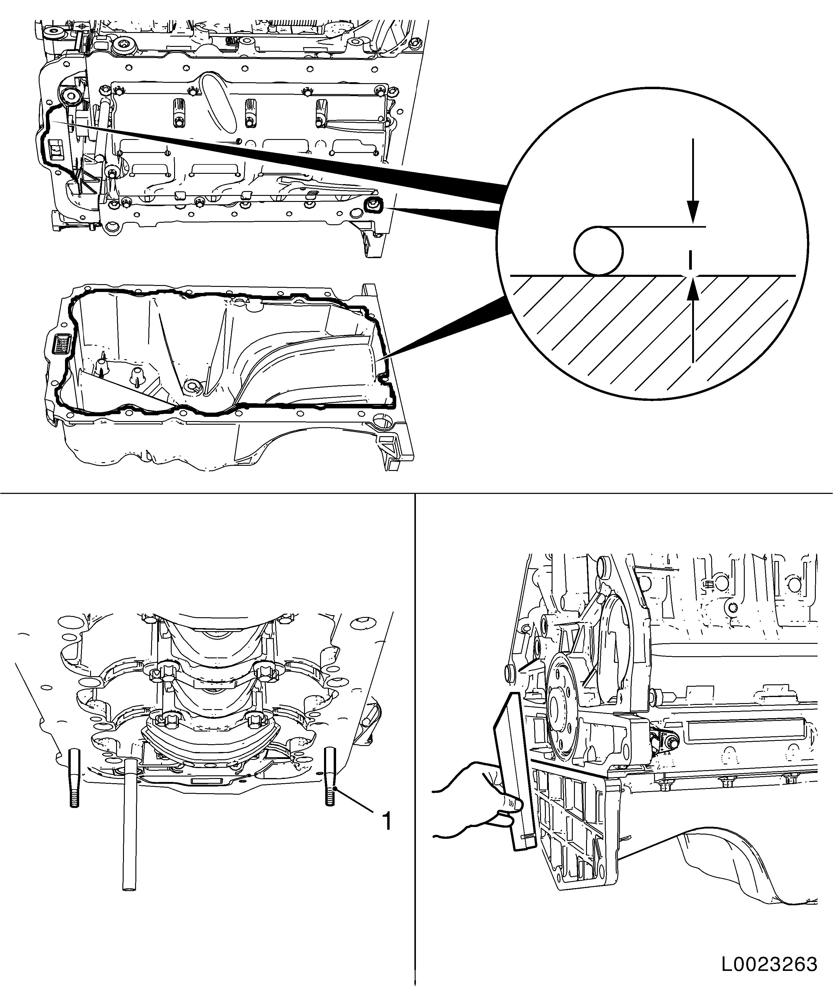
| 22. |
Remove oil pan
Important: Do not damage oil pan
and base place seal surfaces when prising off
|
| • |
Detach oil pan by carefully prising out to position (1)
|
|
|
|
| 23. |
Detach oil baffle plate
|
| 24. |
Rotate engine on engine overhaul stand through 180°
|
|
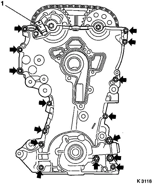
| 25. |
Remove timing case
| • |
Unscrew 15x bolts (arrows)
| – |
Do not damage camshaft sensor (1)
|
|
| • |
Prise out timing case seal ring
Note: Do not damage
sealing surface
|
|
|
|
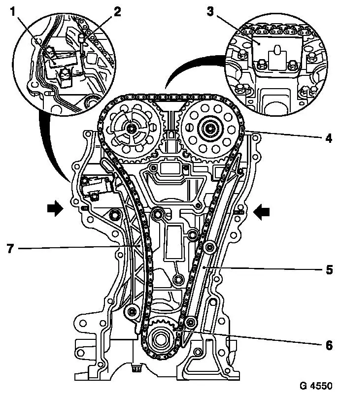
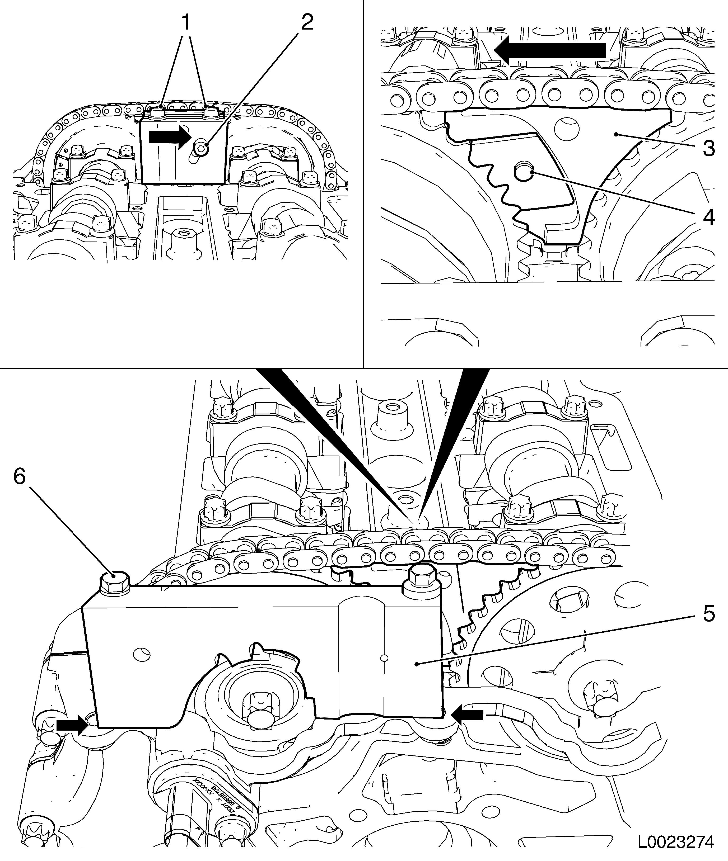
| 26. |
Detach chain drive
| • |
Slacken bolts, camshaft sprockets
| – |
Counterhold the camshafts on the hexagon
|
|
| • |
Lock chain tensioner (1)
|
|
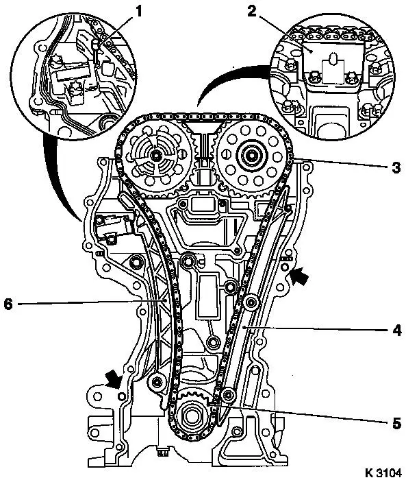
| 27. |
Turn back chain tensioner (1) and lock with KM-955-1 (2)
|
| 28. |
Remove sliding rail (3)
|
| 29. |
Remove guide rail (5)
|
| 30. |
Remove guide rail (7)
|
| 31. |
Remove timing chain (4), drive gear (6) and timing case
gasket
|
|
| 32. |
Rotate engine on engine overhaul stand through 180°
|
| 34. |
Remove crankshaft sensor
Note: Note seal
ring
|
| 35. |
Detach cylinder block base plate
|
| 36. |
Remove con-rod bearing cover
Note: The shear
surfaces of the con-rod and the con-rod bearing cover form a unique
fit and must not be swapped or damaged. Do not lay down on the
shear surfaces
| • |
Mark con-rod bearing cap (1)
|
| • |
Remove con-rod bearing cap
|
|
|
|
| 37. |
Detach crankshaft
| • |
Remove rear crankshaft seal ring
|
| • |
Take out crankshaft and place on wooden blocks
|
|
| 38. |
Remove crankshaft bearing clips
| • |
Mark crankshaft bearing shells
Note: Observe the
correct sequence
|
|
| 39. |
Remove con-rod bearing shells
| • |
Identify con-rod bearing shells
Note: Observe the
correct sequence
|
|
| 40. |
Check all parts for wear, replace if necessary
|
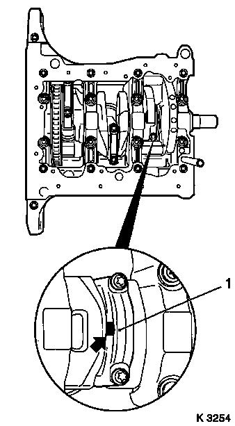
| 41. |
Detach crankshaft pulse sensor disk (1)
|
|
|
 Install
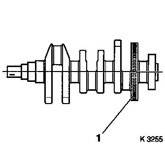
| 42. |
Attach crankshaft pulse pick-up disc
|
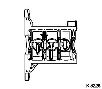
| 43. |
Insert crankshaft bearing shells in cylinder block and in
cylinder block base plate
| • |
Note position of axial bearing (arrow)
|
|
|
|
| 44. |
Insert con-rod bearing shells into con-rods and con-rod bearing
caps
|
| 45. |
Insert crankshaft carefully into cylinder block
Note: The position of
the crankshaft can be corrected by hammering gently on the crank
webs with a rubber mallet
| • |
Coat crankshaft journal with engine oil
|
|
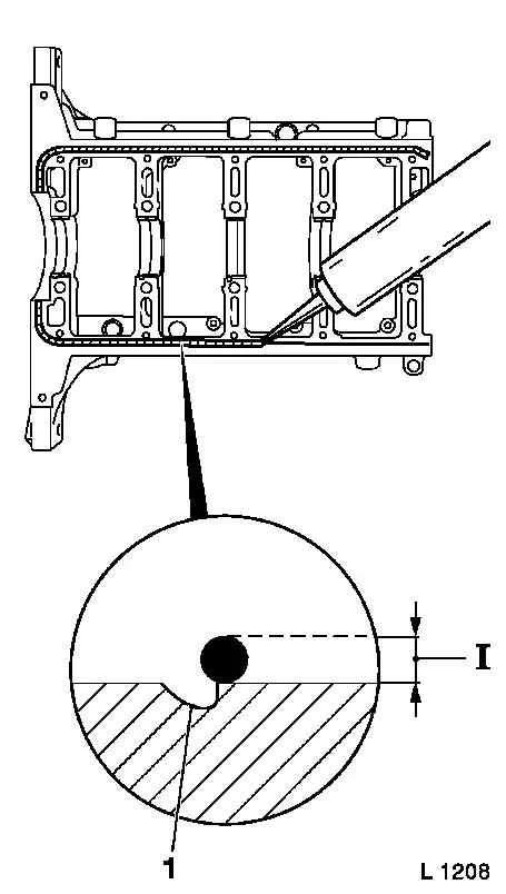
| 46. |
Attach cylinder block base plate to cylinder block with new
bolts
Note: Complete assembly
work within 10 minutes
| • |
Apply sealant to the outer edge of the groove (dimension I = 2
mm)
Note: Do not apply
sealant in groove
|
Important: Observe tightening
sequence
|
| • |
Tighten 8 M8 bolts inside 25 Nm +
60° + 15°
|
| • |
Tighten 10 M6 bolts outside 10 Nm +
60° + 15°
|
| • |
Remove superfluous sealant
|
|
|
|
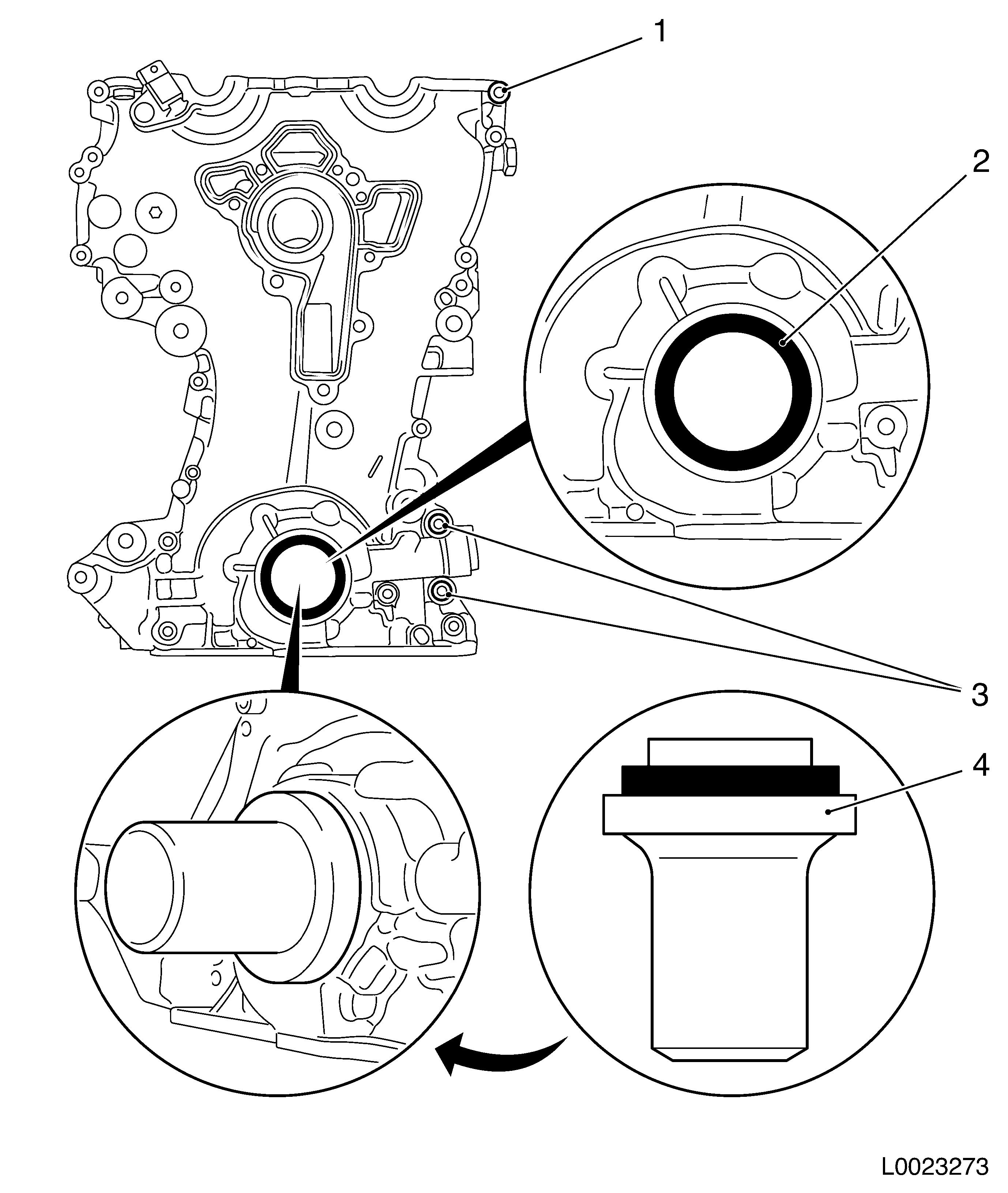
| 47. |
Install crankshaft rear seal ring (1)
| • |
Position KM-235-6 (2) on crankshaft
journal
|
| • |
Slide seal ring onto KM-235-6
|
| • |
Drive in flush using KM-658-1 (3)
|
|
|
|
| 48. |
Attach con-rod bearing cap to con-rod with new bolts
Note: Note installation
position, bead (arrow) on the con-rod bearing cap points towards
the transmission side
| • |
Tighten 6 bolts 13 Nm + 60° +
15°
Note: Only use screws
of size M6.5
|
|
|
| 49. |
Lock crankshaft
| • |
Unscrew crankshaft closure bolt
|
Important: It must be possible to
insert KM-952 smoothly and without major
effort into the crankshaft recess.
|
| • |
Insert KM-952 (1)
| – |
Rotate smoothly on crankshaft dihedral (2) in direction of
engine rotation until KM-952 engages
|
|
|
|
| 50. |
Attach crankshaft sensor
Note: Use new seal
ring
| • |
Fix wiring harness plug
|
|
|
| 51. |
Replace timing case gasket
| • |
Apply 2x sealing bead as shown (2 mm)
Note: After application
of the sealant, the chain drive and timing case must be fitted
within 10 minutes
|
| • |
Place new gasket in position
Note: Note guide
bushings (arrows)
|
|
| 52. |
Attach timing chain
| • |
Insert KM-953 into camshafts
Note: If necessary,
gently adjust camshafts by the hex
|
| • |
Apply timing chain (3) together with drive gear (5)
|
|
| 53. |
Attach timing chain tension rail (6)
| • |
Tighten bolt 20 Nm
Note: Ensure correct
seat of timing chain
|
|
| 54. |
Attach timing chain guide rail (4)
| • |
Tighten 2x bolt 8 Nm
Note: Ensure correct
seat of timing chain
|
|
| 55. |
Attach timing chain sliding rail (2)
|
| 56. |
Relieve tension on chain tensioner
|
|
|
| 57. |
Attach timing case.
Note: Note guide
bushings and camshaft sensor
| • |
Tighten 13x bolt M6 (1) 8 Nm
|
| • |
Tighten 2x M10 bolt (3) 35 Nm
|
|
| 58. |
Replace front crankshaft sealing ring (2)
| • |
Drive in flush using KM-960
|
|
|
|
| 59. |
Fit torsional vibration damper (6)
| • |
Insert torsional vibration damper in oil pump rotor hex head
(2) and crankshaft dihedral (1)
Note: Marking on the
torsional vibration damper must align with the marking on the
timing case
|
| • |
Check for correct torsional vibration damper seating
| – |
Measure distance between torsional vibration damper and edge of
timing case (dimension a = 5,5 mm)
|
|
| • |
Screw in torsional vibration damper bolt (7)
|
| • |
Tighten torsional vibration damper bolt 150 Nm
| – |
Counterhold it with EN-49979 (4)
together with KM-956-1 (5)
|
|
|
|
| 60. |
Fix 2x camshaft sprocket
| • |
Attach EN-49977-200 (3)
Note: Press EN-49977-200 in direction of arrow so that the
teeth (4) engage in the teeth of the intake camshaft sprocket
without play
| – |
Tighten 2x fastening bolt (1)
|
| – |
Tighten adjusting bolt (2)
Note: Press EN-49977-200 in direction of arrow when
tightening
|
|
|
| 61. |
Adjust and fix phase sensor disc
| • |
Rotate phase sensor disc until EN-49978 (5) can be inserted
Note: EN-49978 must rest on the surfaces shown (arrows)
without play
|
| • |
Tighten 2x fastening bolt (6)
|
|
| 62. |
Tighten 2x camshaft sprocket 50 Nm +
60°
| • |
Counterhold with open-end wrench against the hexagon of the
camshafts
|
|
| 63. |
Remove all special tools: KM-952 ,
EN-953 , EN-49977-200 , EN-49978
|
|
|
| 65. |
Repeat adjustment procedure if necessary
|
| 66. |
Remove locking tool
| • |
KM-952 , KM-953 , EN-49978
|
|
| 67. |
Insert crankshaft sealing plug and tighten 50 Nm
Note: Use new seal
ring
|
| 68. |
Attach coolant pump together with thermostat housing
| • |
Insert 9x bolt 8 Nm
Note: Note different
bolt lengths
|
|
| 69. |
Attach 3 coolant hoses to coolant pump
|
| 70. |
Clip engine management wiring harness into cylinder head
cover
| • |
Connect 3 wiring harness plugs
| – |
Camshaft sensor, coolant temperature sensor, oil pressure
sensor
|
|
|
| 71. |
Attach coolant pump belt pulley
| • |
Insert 3x bolt and tighten 22 Nm
Note: Counterhold with
open-end wrench on flange
|
|
| 72. |
Rotate engine on engine overhaul stand through 180°
|
| 73. |
Attach oil baffle plate
|
|
| 74. |
67. Install oil pan
| • |
Apply sealant (dimension I = 2 mm)
Note: Oil pan
installation must take place within 10 minutes
| – |
For the bolt hole shown
|
|
| • |
Rotate 2x EN-49980 (1) into the
positions shown
|
Important: When positioning the
oil pan, it is necessary to ensure that the sealing bead is not
wiped away.
|
| • |
Carefully apply the oil pan
Note: Pass EN-49980 through corresponding bolt holes
|
| • |
Insert 4x bolt, offset diagonally
|
| • |
Adjust oil pan with rubber mallet and straightedge
Note: Straightedge must
rest on the oil pan and cylinder block without play
|
|
|
| 75. |
Rotate engine on engine overhaul stand through 180°
|
| 76. |
Attach cylinder head cover (1)
| • |
Apply sealant (dimension I = 2 mm)
Note: Complete assembly
work within 10 minutes
|
| • |
Attach 2x engine vent hose
|
|
| 77. |
Attach ignition module
| • |
Connect ignition module wiring harness
|
|
|
|
| 78. |
Install alternator
| • |
Insert alternator into bracket
|
| • |
Attach 2x screwed connection 35
Nm
|
| • |
Attach alternator wiring harness
|
|
| 79. |
Attach ribbed V-belt tensioner -
| • |
Tighten bolt (M8) 20 Nm
|
| • |
Tighten bolt (M10) 55 Nm
|
|
| 80. |
Insert ribbed V-belt
Note: Ensure correct
running direction and installation position
| • |
Release ribbed V-belt tensioner
|
|
| 81. |
Attach engine bracket right
|
| 82. |
Top up engine oil.
| • |
Observe specified engine oil quantity
|
|
| 83. |
Detach engine from engine overhaul stand
| • |
Attach KM-2358 to 3x engine transport
shackle
|
| • |
Hitch engine up to workshop crane.
|
| • |
Lower engine onto wooden pallet
|
| • |
Detach KM-2358 from 3x engine
transport shackle
|
|
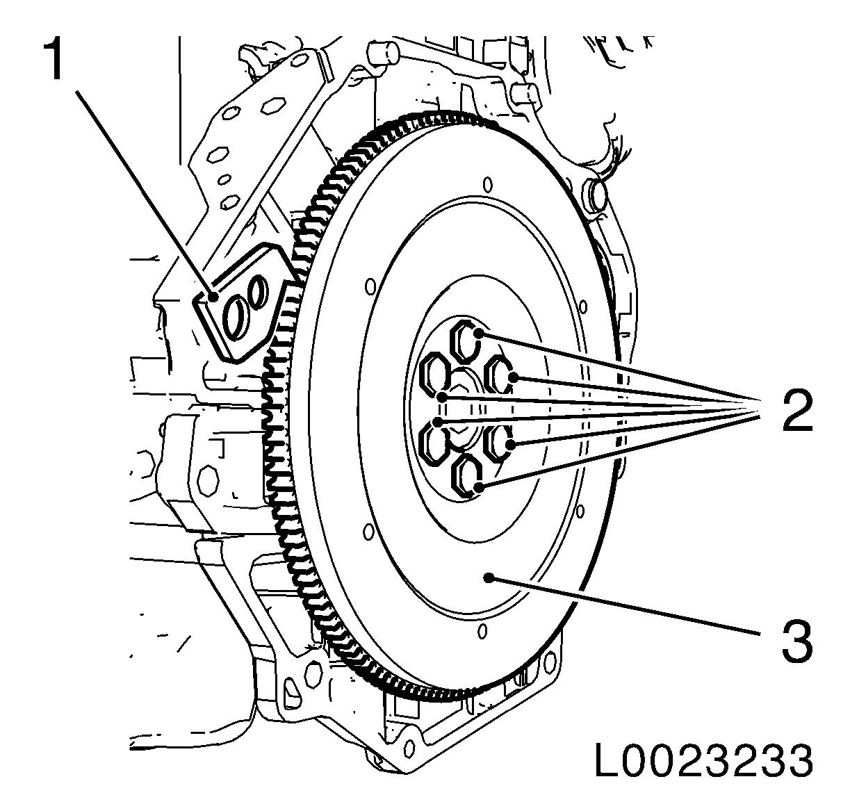
| 84. |
Fit flywheel
| • |
Clean 6x thread in crankshaft
|
| • |
Tighten 6x new bolt 35 Nm +60
°
|
|
| 85. |
Attach clutch and thrust plate
|
| 86. |
Attach manual transmission to engine
|
|
