|
Transmission, Remove and Install (AF13-II)
 Remove Remove
| 1. |
Remove front axle body
|
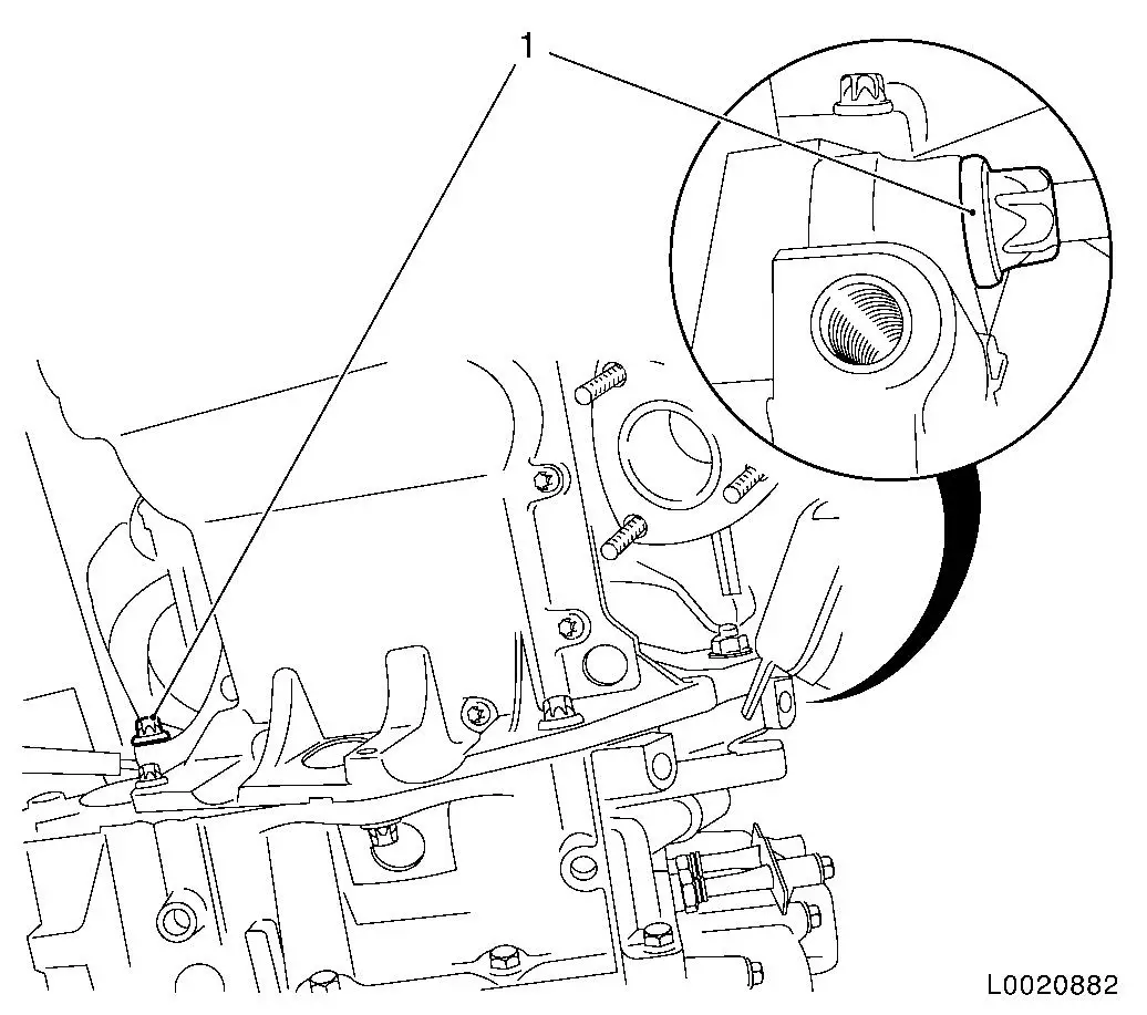
| 2. |
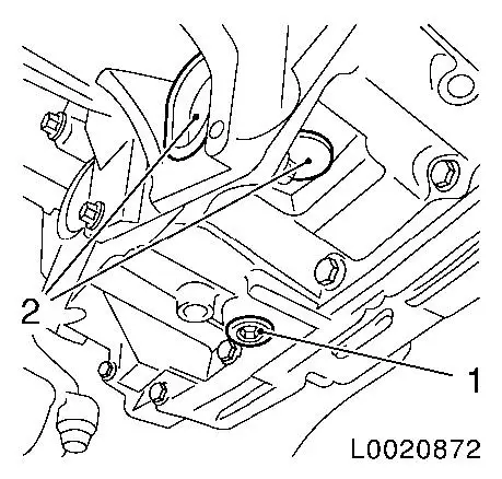
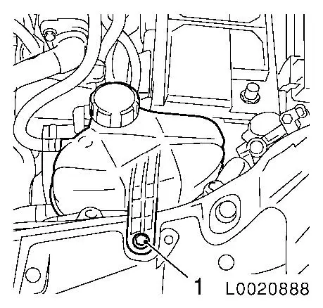
Drain off transmission fluid
| • |
Unscrew fluid drain bolt (1)
|
| • |
Catch fluid in suitable container
|
| • |
Tighten new fluid drain bolt with new seal ring 40 Nm
|
|
| 3. |
Detach 2 covers (2) from transmission
|
|
|
| 4. |
Remove axle shafts from transmission 
| • |
Attach axle shafts to vehicle underbody
|
|
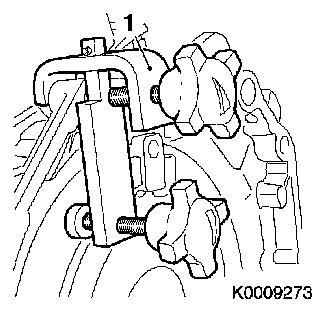
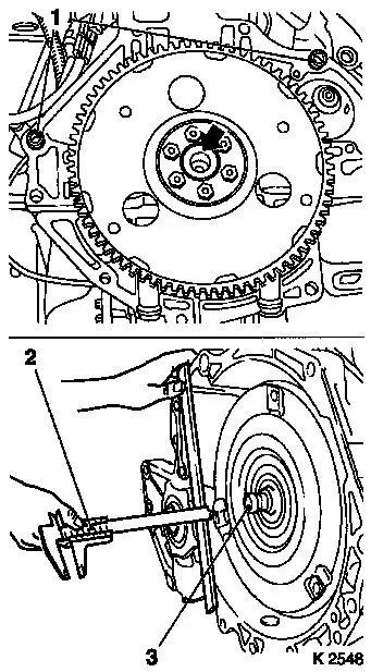
| 5. |
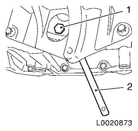
Detach converter from drive disk
| • |
Lock drive disk with KM-911 (2)
|
| • |
Unscrew 3x bolts (1)
Note: Rotate drive disk
another 120°.
|
|
|
|
| 6. |
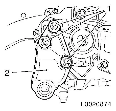
Remove rear engine damping block bracket (2)
|
|
|
| 7. |
Control unit - remove electronic gear shifting
|
| 8. |
Control unit bracket - remove electronic gear shifting
|
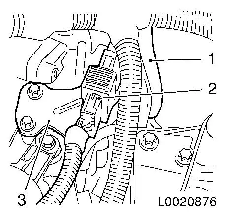
| 10. |
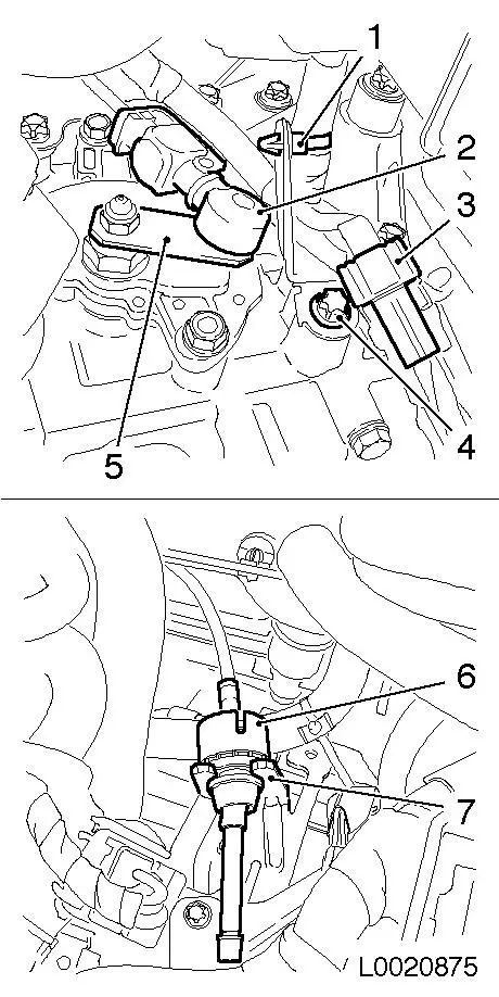
Release and disconnect selector lever position switch wiring
harness plug (3)
|
| 11. |
Remove wiring harness bracket
| • |
Unclip wiring harness (1)
|
|
| 12. |
Detach selector lever actuation cable (2)
| • |
Remove actuation cable from counterhold (7)
| – |
Pull sleeve (6) back and remove actuation cable upward from
bracket
|
|
| • |
Press lever actuation cable (5) off selector lever position
switch
|
|
|
|
| 13. |
Remove engine/transmission control wiring harness
| • |
Release wiring harness plug (2) and disconnect
|
| • |
Unclip wiring harness from bracket (3)
|
|
| 14. |
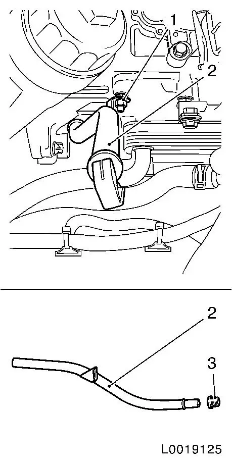
Pull off transmission vent hose (1)
|
|
|
| 15. |
Remove coolant expansion tank
| • |
Unclip tank and lay aside
|
|
|
|
| 17. |
Remove fluid filler tube (2)
| • |
Remove fluid filler tube from transmission
|
|
|
|
| 18. |
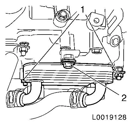
Detach fluid cooler from transmission
|
|
|
| 19. |
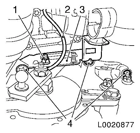
Release transmission at top
| • |
Remove earthing cable (2)
|
| • |
Unscrew 3x bolt (4)
| – |
Remove wiring harness bracket (3)
|
|
|
|
|
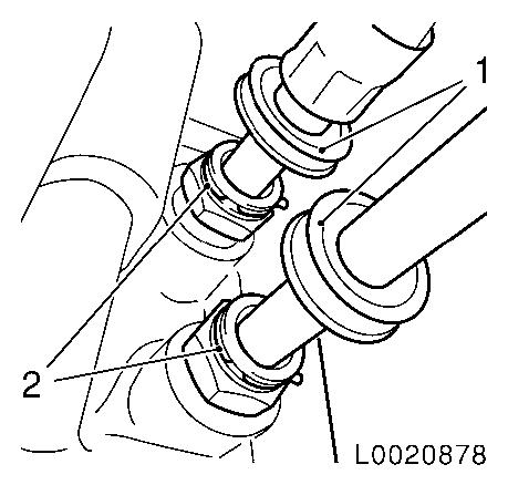
| 21. |
Detach 2 fluid cooler lines from transmission
Note: Place collecting
pan underneath.
| • |
Pull off 2 protective rings (1)
|
| • |
Prise off 2 retaining clamps (2)
Note: Prise retaining
clamp from quick-release connection with a small screwdriver
|
| • |
Pull off 2 fluid cooling lines
|
| • |
Place fluid cooler with fluid cooling lines aside and
secure
|
|
|
|
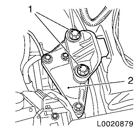
| 22. |
Remove the engine damping block to the left of the engine
damping block retaining base (2)
| • |
Lower engine and transmission by approximately 5 cm using EN 47649
Note: Ensure that
attached parts and wiring harnesses are not damaged.
|
|
|
|
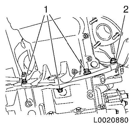
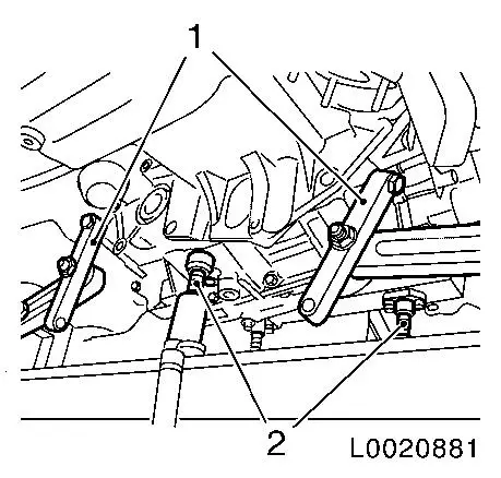
| 23. |
Release transmission at the bottom
| • |
Detach transmission from oil pan
| – |
Unscrew 3 M10 bolts (1)
|
|
| • |
Unscrew screw connection (2)
|
|
|
|
|
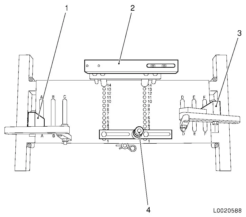
| 24. |
Place transmission fixture DT-47648
on KM-904 and assemble as shown in
illustration:
|
Component
|
Position on base plate
|
Designation
|
|
DT-47648-2
(4)
|
2
|
Converter housing support
|
|
DT-47648-3
(2)
|
14
|
Transmission housing support
|
|
DT-47648-5 left
(1)
|
A
|
Rear transmission support with pivot arm
|
|
DT-47648-5 right
(3)
|
F
|
Support with pivot arm, transmission, front
|
|
|
Important: Pay strict attention
to manufacturer's notice for transmission fixture DT-47648 .
|
| 25. |
Attach transmission fixture DT-47648
to transmission
Note: Loosen all screw
connections of the pivot arms and supports to the base plate before
placing under load. Rotate the supports for the converter housing
and transmission housing as far down as possible by way of the
spindles.
| • |
Align the transmission fixture DT-47648 beneath the transmission
|
| • |
Attach 2x swivel arm (1) to transmission
|
| • |
Tighten screw connections of the pivot arms from the
transmission to the base plate
Note: Align the pivot
arms so that as a little lever force as possible is created.
|
| • |
Position the supports for the converter housing and
transmission housing on the transmission
| – |
Screw the spindles (2) upward
|
|
| • |
Tighten screw connections on the supports
|
|
|
|
|
Important: Ensure that the
converter remains in the transmission
|
| 26. |
Removing transmission
| • |
Unscrew 2 M12 bolts (1)
|
| • |
Press the engine away from the transmission and slowly lower
the hydraulic jack
Note: Do not damage
wiring harnesses and attaching parts
|
|
|
| 27. |
Use KM-6388 (1) to secure torque
converter so it does not fall
|
|
|
Important: Do not damage
attaching parts when laying transmission down.
|
| 28. |
If necessary, detach the transmission from the transmission
fixture DT-47648
|
| 29. |
If transmission is being replaced:
| • |
Drain fluid cooler as much as possible
|
| • |
Blow out fluid cooler with air at low pressure
|
| • |
Blow out fluid cooling lines at connections in both directions
with air at low pressure
|
| • |
Convert the attached parts
|
|
 Install
| 30. |
If necessary, attach the transmission to the transmission
fixture DT-47648
Note: Pay strict
attention to the manufacturer's notice for DT-47648 .
Before installing the transmission: Coat the centring pin (arrow)
in the crankshaft thinly with grease. When replacing transmission,
ensure that both guide bushings (1) sit in the engine flange.
|
| 31. |
Check centring pin (3) of converter for frictional rust
|
| 32. |
Measure distance between connecting threads of converter and
mating surface of transmission housing with calliper gauge (2)
| • |
Spacing distance of AF13-II approx. 12 mm
|
|
| 33. |
Tap 3 threads in converter
|
|
|
|
| 35. |
Lift transmission with hydraulic jack and transmission fixture
A DT-47648 and align
| • |
Place transmission so that it is in even contact with the
engine
Note: Ensure it is
seated perfectly.
Do not damage wiring harnesses and attaching parts
|
|
| 36. |
Fasten transmission to engine using 2 bolts
| • |
Tighten 2 M12 bolts (1) 60 Nm
|
|
| 37. |
Detach transmission fixture DT-47648
from transmission
| • |
Lower hydraulic jack with transmission fixture DT-47648 and remove
|
|
|
| 38. |
Fasten transmission at the bottom
| • |
Install transmission on fluid sump
| – |
Tighten 3 M10 bolts (1) 40 Nm
|
|
| • |
Tighten screw connection (2) 40
Nm
|
|
|
|
| 39. |
Attach converter to drive disk
| • |
Lock drive disk with KM-911 (2)
|
| • |
Tighten 3 bolts (1)
Note: Insert bolts with
locking compound.
Rotate drive disk another 120°.
| – |
Step 1: tighten 3 bolts uniformly with 20 Nm
|
| – |
Step 2: tighten 3 bolts with 45 Nm +
20° + 25°
|
|
|
| 40. |
Attach 2 covers to transmission
|
|
|
| 41. |
Move engine and transmission into installation position with
EN 47649
Note: Do not damage
wiring harnesses and attaching parts
|
| 42. |
Attach the engine damping block on the left to the engine
damping block retaining base (2)
| • |
Tighten 2 bolts (1) 80 Nm
45°
|
|
|
|
| 44. |
Fasten transmission at the top
| • |
Tighten 3 bolts (4) 60 Nm
| – |
Insert wiring harness bracket (3)
|
|
| • |
Attach earthing cable (2)
|
|
|
|
| 45. |
Install fluid filler tube (2)
| • |
Insert new seal ring (3) into fluid filler pipe with assembly
grease
|
| • |
Push fluid filler tube into transmission until stop
|
|
|
|
| 47. |
Attach 2 fluid cooler lines to transmission
Note: Use new seal
rings.
| • |
Insert 2 retaining clamps (2)
|
| • |
Insert 2 fluid cooling lines
Note: Ensure that the
fluid cooling lines engage audibly.
|
| • |
Push on 2 protective rings (1)
|
|
|
|
| 48. |
Install 2 axle shafts in transmission
|
| 49. |
Attach fluid cooler to transmission
| • |
Tighten 2 nuts (1) 20 Nm
|
|
|
|
| 50. |
Attach coolant expansion tank
|
|
|
| 51. |
Attach engine/transmission control wiring harness
| • |
Clip wiring harness into bracket (3)
|
| • |
Connect and lock wiring harness plug (2)
|
|
| 52. |
Push on transmission vent hose (1)
|
|
|
| 53. |
Attach selector actuation cable (2)
| • |
Attach actuation cable to counterhold (7)
| – |
Pull sleeve (6) back and insert actuation cable from above into
bracket
|
|
| • |
Clip lever actuation cable (5) on selector lever position
switch
Note: Ensure that the
cable engages audibly.
|
|
| 54. |
Install wiring harness bracket
| • |
Clip in wiring harness (1)
|
|
| 55. |
Connect and lock selector lever position switch wiring harness
plug (3)
|
| 56. |
Adjust selector actuation cable
|
|
|
| 57. |
Install battery tray and battery
|
| 58. |
Control unit bracket - install electronic gear shifting
|
| 59. |
Control unit - install electronic gear shifting
|
| 60. |
Attach rear engine damping block bracket (2)
| • |
Tighten 3 new bolts (1) 80 Nm +
45°
|
|
|
|
| 61. |
Install front axle body
|
| 62. |
Transmission Fluid Level, Check and Correct
|
| 63. |
Program volatile memories
|
|
