|
Main shaft, dismantle and reassemble (F13+/F13+
MTA)
Note: Transmission
remains installed.
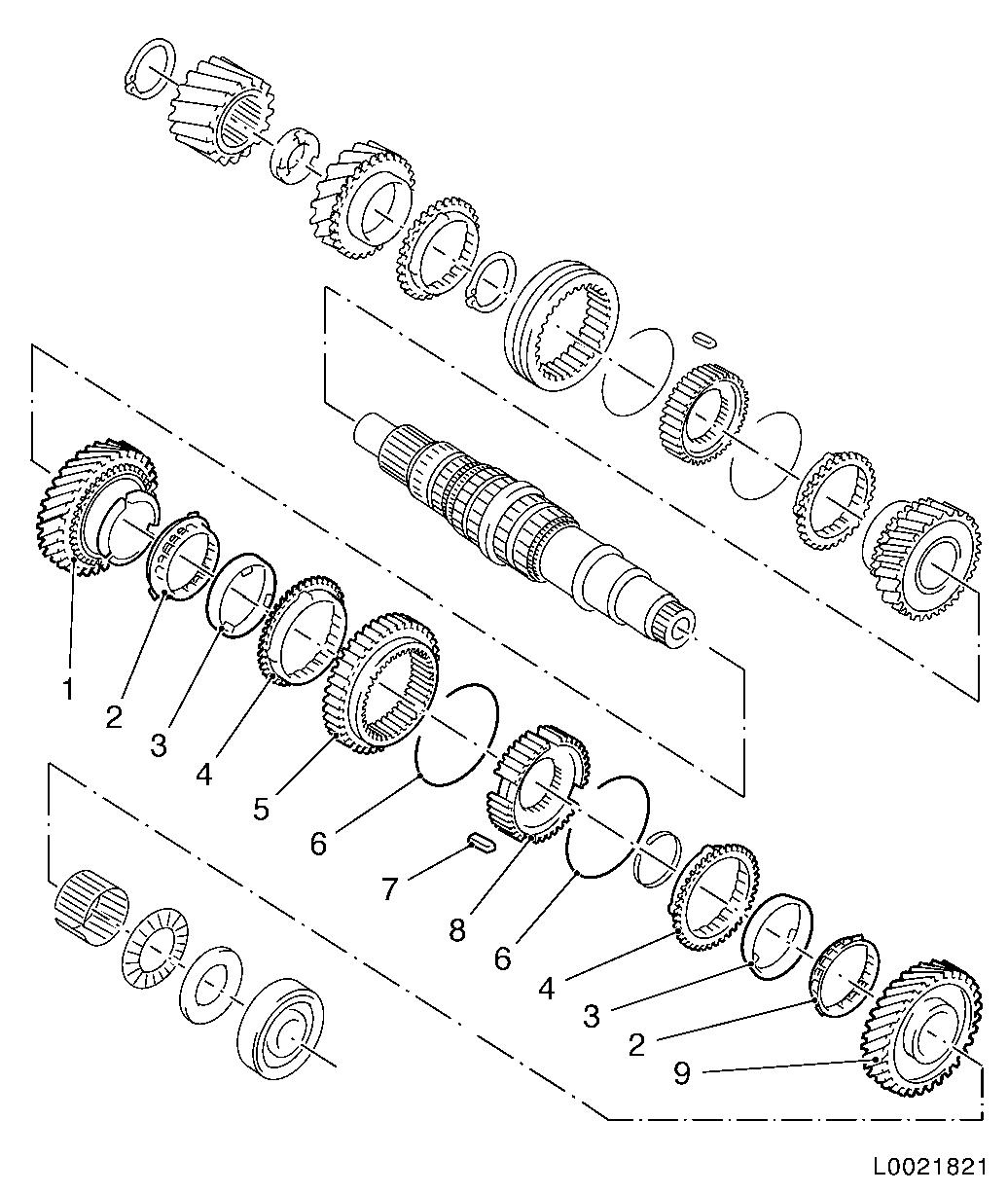
Overview main shaft
 Remove Remove
|
| 2. |
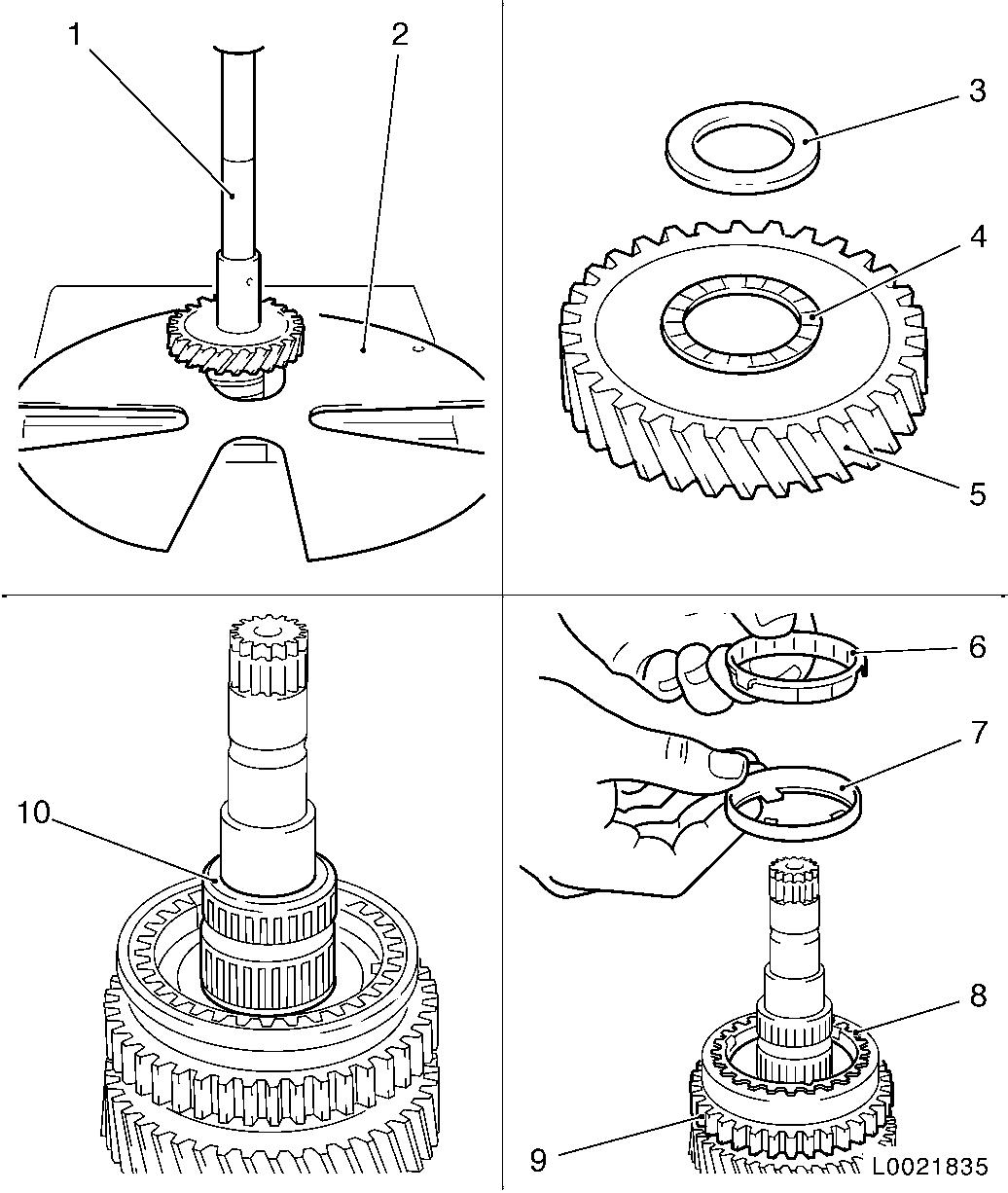
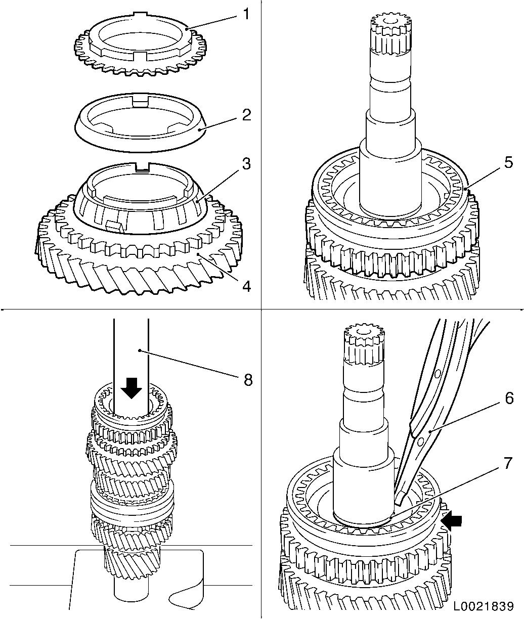
Remove main shaft
Note: In case of damage
to the gear wheels, always replace the toothed gear block as
well.
|
| 3. |
Press out distance washer (3), axial needle bearing (4) and
gear wheel 1st gear (5) with KM-307-B
(2)
|
| 4. |
Remove needle bearing (10) for gear wheel 1st gear from main
shaft
Note: If present.
|
| 5. |
Remove inside synchronising ring (6), intermediate ring (7) and
outside synchronising ring (8) for gear wheel 1st gear from
synchroniser body assembly (9)
|
|
|
| 6. |
Remove lock ring for synchroniser body assembly (1) 1st/2nd
gear with lock ring pliers (2) KM-396
|
| 7. |
Remove synchronising spring (6), synchroniser sleeve (7) and
sliders (3 and 5) from synchroniser body (4)
|
| 8. |
Press synchroniser body (14), inside synchronising ring, (13),
intermediate ring (12) and outside synchronising ring (11) for gear
wheel 2nd gear (10) out with KM-307-B (9)
from main shaft (arrow)
|
|
|
| 9. |
Remove lock ring (1) in front of drive wheel (driving) from
main shaft
|
| 10. |
Press drive wheel (driving (3) out with KM-307-B (4) from main shaft (arrow)
Note: Always replace
drive wheels (driving and driven) in pairs.
|
|
|
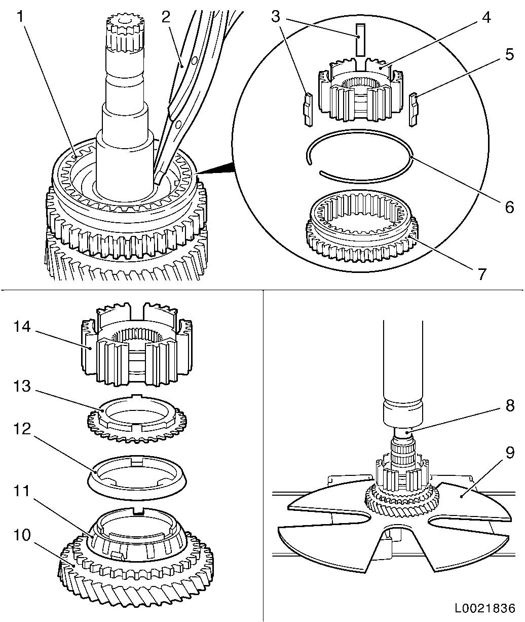
| 11. |
Place KM-307-B (1) in the groove of
the gear wheel 4th gear (2)
|
| 12. |
Press gear wheel 4th gear and distance washer (4) out with
KM-307-B from main shaft
|
| 13. |
Remove needle bearing (11) (if present), synchronising ring
(gear wheel 4th gear) (10), synchroniser sleeve (9), synchronising
spring and sliders from main shaft
|
| 14. |
Remove lock ring (6) with lock ring pliers
|
| 15. |
Press synchroniser body (7) 3rd/4th gear, synchronising ring
and gear wheel 3rd gear (8) out with KM-307-B from main shaft
|
|
 Install
|
| 17. |
Dip all parts in transmission oil before installation
|
| 18. |
Check removed parts for damage, wear; replace if necessary
|
| 19. |
Lubricate all bearing holes and seating surfaces with
transmission oil before installation
|
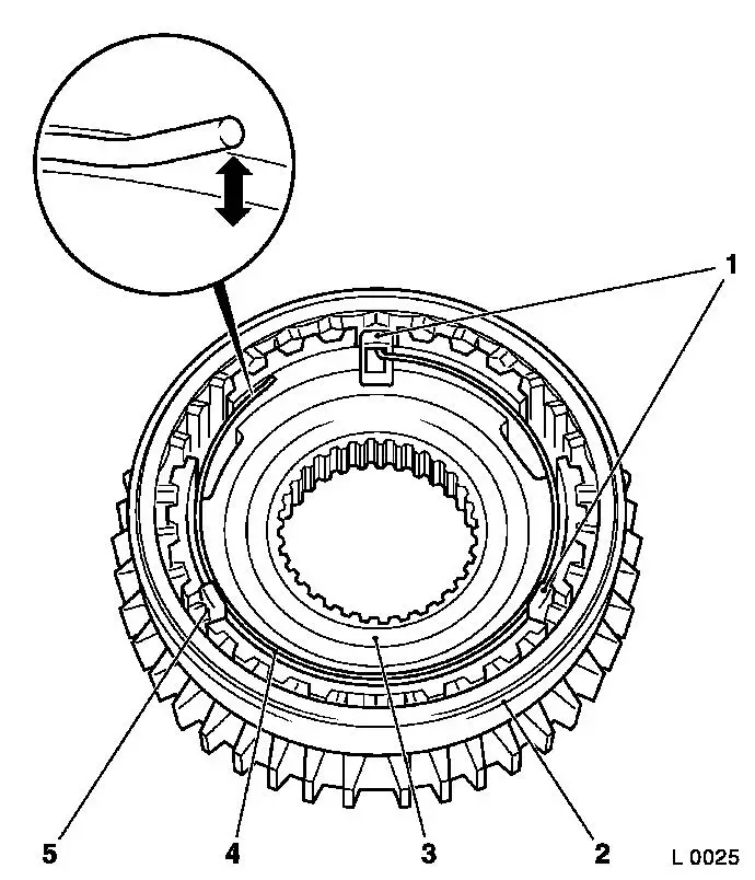
| 20. |
Transmission has a 3-cone synchronisation for the 1st and 2nd
gear:
| 1. |
Gear wheel 2nd gear |
| 2. |
Inside synchronising rings |
| 3. |
Intermediate rings |
| 4. |
Outside synchronising rings |
| 5. |
Synchroniser sleeve |
| 6. |
Synchronising springs |
| 7. |
Sliders |
| 8. |
Synchroniser body |
| 9. |
Gear wheel 1st gear |
|
|
|
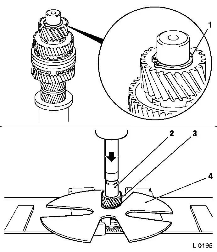
| 21. |
Insert synchroniser body (3) in synchroniser sleeve (2)
Note: Assembly of
synchroniser bodies 1st/2nd gear and 3rd/4th gear can only be
pressed onto the main shaft in the assembled state.
|
| 22. |
Insert sliders (1) and (5)
| • |
with the open side to the synchroniser body
|
|
| 23. |
Insert 2x synchronising spring (4)
Note: Ensure that with
correct installation position, the free end of the synchronising
spring lifts up from the synchroniser body (arrow). If this is not
the case, turn synchronising spring 180° and reinstall.
| • |
The bent end of the synchronising spring engages with a
slider
|
|
|
|
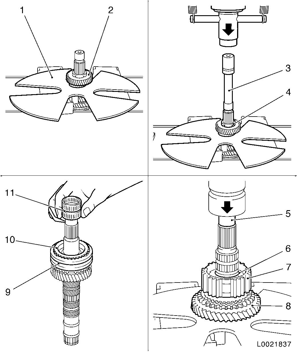
| 24. |
Install needle bearing (2) for gear wheel 3rd gear on main
shaft (1)
Note: If present.
|
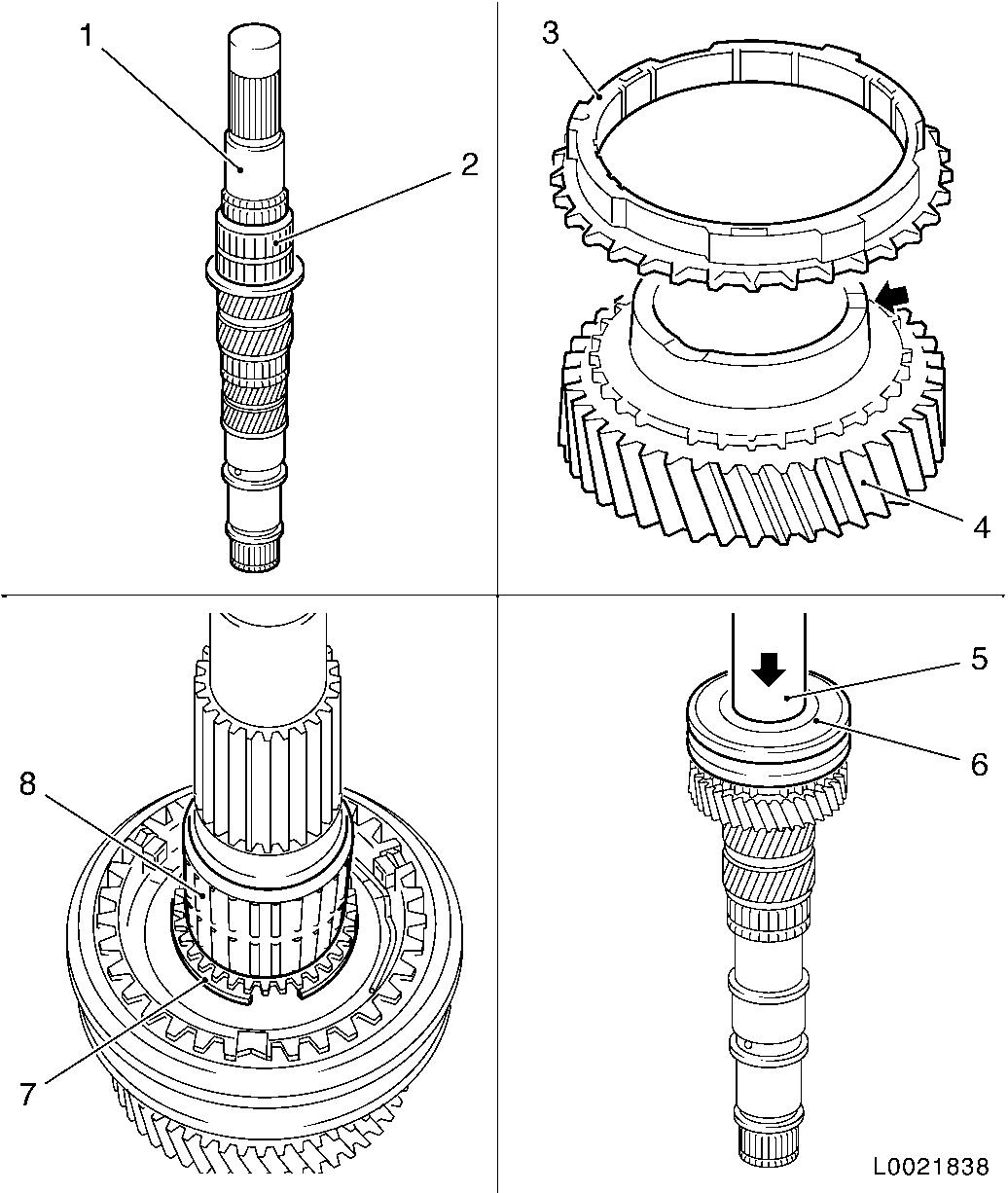
| 25. |
Move gear wheel 3rd gear (4) from drive wheel side to main
shaft
| • |
Cone (arrow) points in the direction of the drive wheel
|
|
| 26. |
Place synchronising ring (3) on cone gear wheel 3rd gear
|
| 27. |
Press assembly of synchroniser body 3rd/4th gear (6) with KM-373-1 (5) on main shaft
|
| 28. |
Mount synchroniser body lock ring (7) with KM-396
|
| 29. |
Install needle bearing (8) for gear wheel 4th gear on main
shaft
Note: If present.
|
|
|
| 30. |
Install synchronising ring (3) and gear wheel 4th gear (2) on
main shaft
|
| 31. |
Place distance washer (1) on main shaft
| • |
Four grooves (arrow) must point to gear wheel 4th gear
|
|
| 32. |
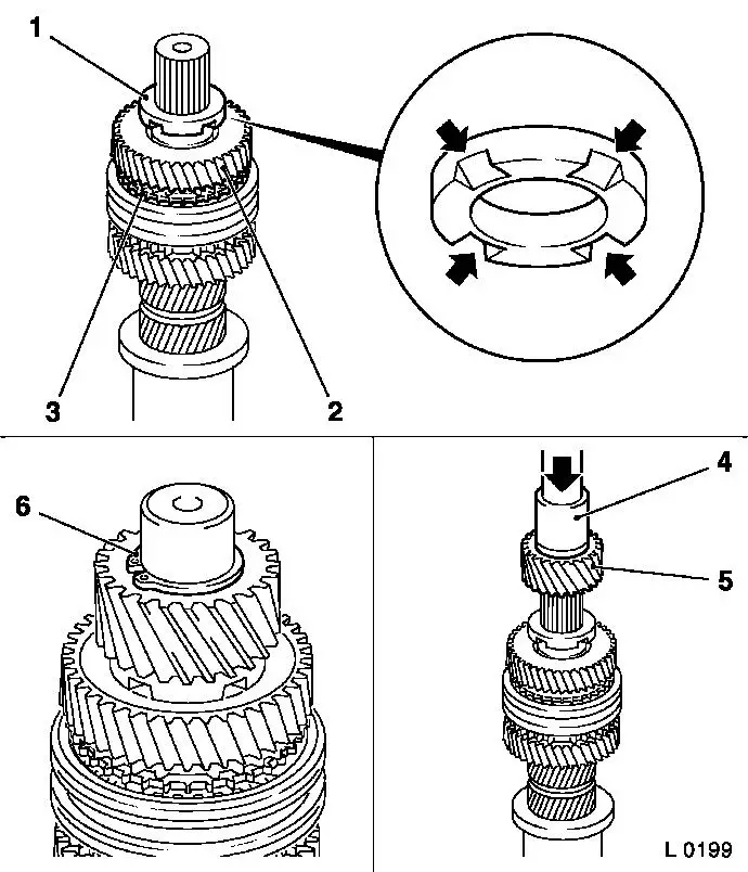
Press drive wheel (5) onto main shaft with KM-473 (4)
Note: Always replace
drive wheels in pairs.
| • |
Collar must point to distance washer
|
|
| 33. |
Install new lock ring (6) in front of drive wheel
|
|
|
| 34. |
Move gear wheel 2nd gear (4) onto drive shaft
|
| 35. |
Place inner synchronising ring (3) on cone of gear wheel
| • |
Noses must sit in grooves of gear wheel
|
|
| 36. |
Place intermediate ring (2) on inner synchronising ring
|
| 37. |
Place outer synchronising ring (1) on intermediate ring
| • |
Grooves must sit on noses of inner synchronising ring
|
|
| 38. |
Place synchroniser body assembly (5) on main shaft
|
| 39. |
Press synchroniser body assembly onto main shaft with KM-514 (8)
| • |
Noses of outer synchronising ring must be aligned with grooves
of synchroniser body
|
| • |
Shift fork groove (arrow) points to ball bearing seat
|
|
| 40. |
Insert new lock ring (7) with lock ring pliers (6) in front of
synchroniser body 1st/2nd gear
|
|
|
| 41. |
Place outer synchronizing ring (3) with noses in grooves of
synchroniser body (4)
|
| 42. |
Place intermediate ring (2) on the outer synchronising ring
|
| 43. |
Place inner synchronising ring (1) on intermediate ring
| • |
Noses must engage in grooves of outer synchronising ring
|
|
| 44. |
Place needle bearing 1st gear (5) on main shaft
Note: If present.
|
| 45. |
Move gear wheel 1st gear onto needle bearing
| • |
Grooves must sit on noses of intermediate ring
|
|
| 46. |
Place axial needle bearing (8) on gear wheel 1st gear (7)
| • |
Place distance washer (9) on needle bearing
|
|
| 47. |
Press distance washer onto main shaft with KM-473 (6)
|
|
| 48. |
All gear wheels must turn easily
|
|
