|
Rear Differential, Assemble
|
 Assemble
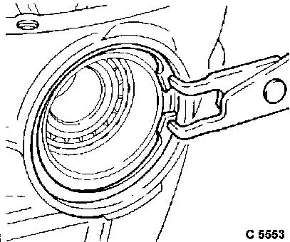
Press outer ring of outer drive pinion bearing to stop in
differential housing using KM-305 (1) and KM-621-10 (2).
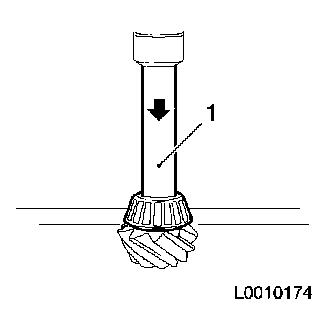
Press tapered roller bearing of inner drive pinion bearing onto
drive pinion gear using KM-625 (1).
|
|
|
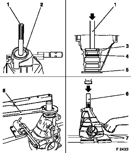
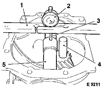
Place KM-621-3 (4) (measuring disc, coloured black to avoid
confusion) in rear differential housing and press in outer ring of
inner drive pinion bearing to stop in differential housing using
KM-305 (1) in conjunction with KM-621-11 (3), ensuring that shim is
correctly seated. Place KM-621-16 (5) underneath when
installing.
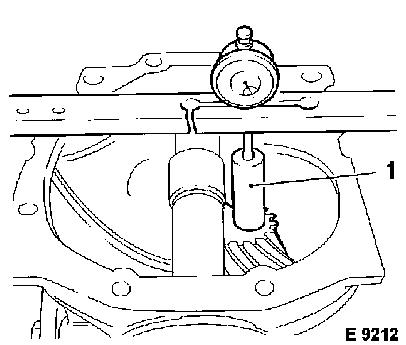
Coat bearings and their running surfaces with special fluid
before assembly. Insert drive pinion gear in rear differential
housing without tension sleeve and press on outer bearing with
KM-625 (6), supporting drive pinion gear on suitable block of wood
(7). If present, replace O-ring in flange.
Place flange on splines of drive pinion gear and screw on
fastening nut, counterholding flange with KM-623 (8).
|
|
|
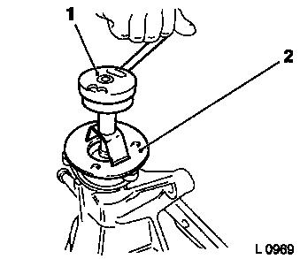
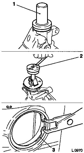
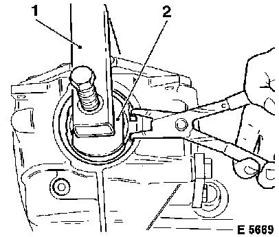
Progressively tighten fastening nut of input flange and use
Friction Measuring Instruments MKM-536-A (1) and KM-885 (2) to
check the bearing preload.
 Inspect
Permissible bearing pre-tension with
new bearings:
|
100 Ncm – 170 Ncm (1.0 Nm – 1.7 Nm / 0.75 –
1.25 lbf. ft.).
|
|
Target value – 150 Ncm (1.5 Nm / 1.11 lbf. ft.).
|
|
|
|
 Measure
|
Check height of drive pinion gear.
|
|
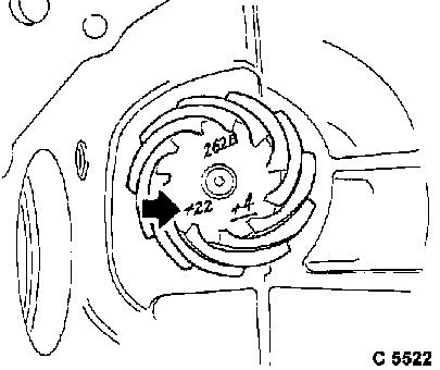
The drive pinion gear is adjusted according to the engraved
check number (arrow).
|
Explanation:
|
+ 22
|
- Check number, states how many hundredths of a millimetre
|
|
|
lower the drive pinion must be, measured from the zero line.
|
|
262 B
|
- Pairing number for drive pinion gear and ring gear.
|
|
+ 4
|
- Underlined number for customer services is irrelevant.
|
|
|
|
Insert KM-621-1-A (5) in differential housing.
|
|
Place KM-621-2 (4) centrally on drive pinion gear.
|
|
Gauge MKM-571-B (2) with probe extension
|
|
Insert Measurement Rail KM-238-2 (1) and when highest point is
attained on Measuring Drift KM-621-1-A (5) set to "0".
|
|
|
|
Move measuring rail until probe of gauge sits on Calibration
Drift KM-621-2 (1). Read off gauge and determine how much deeper
the calibration drift is relative to the measuring drift.
|
|
The thickness of the shim is calculated as follows:
The difference determined with the dial gauge (e.g. 0.39 mm) is
added to the thickness of the Shim KM-621-3 inserted on assembly.
The thickness of Shim KM-621-3 is 3.25 mm.
|
|
|
3.25 mm
|
|
|
+
|
0.39 mm
|
|
|
|
3.64 mm
|
The total play to be bridged with the shim is thus 3.64 mm.
As the pinion gear has an oversize of 0.22 mm, this amount has
to be subtracted from the total play.
|
|
|
3.64 mm
|
|
|
-
|
0.22 mm
|
|
|
|
3.42 mm
|
The thickness of the shim in this example is therefore 3.42
mm.
 Remove Remove
Remove drive bevel gear again.
Press the outer race of the inner bearing out of the
differential housing.
 Install
Once correct shim has been inserted, press in the outer race
– check shim is in correct position.
Lightly oil both taper roller bearings with special oil before
assembly. Place new clamping sleeve on drive bevel gear. Insert
drive bevel gear in differential housing. Press on bearing, as
described above.
|
Caution
When assembling sealing ring with KM-629-1 (1), the sealing lip
facing the input flange will be damaged. To avoid this happening,
modify KM-629-1 as is described in operation for "Sealing Ring
– Drive Bevel Gear, Replace" and modify the tool drawing in
KM-629-1-A as is appropriate.
Assemble
Drive home drive bevel gear sealing ring with KM-629-1-A (1)
flush into differential housing, however, before assembly, coat
sealing lip with special oil. Lift input flange by progressively
tightening nuts. You should continuously check the bearing preload
using Friction Measuring Instruments MKM-536-A (2) and KM-885.
|
|
|
Caution
Permissible bearing pre-tension with new bearings:
|
100 Ncm – 170 Ncm (1.0 Nm – 1.7 Nm / 0.75 –
1.25 lbf. ft.).
|
|
The upper tolerance limit is the target
|
Install
|
Install differential.
|
|
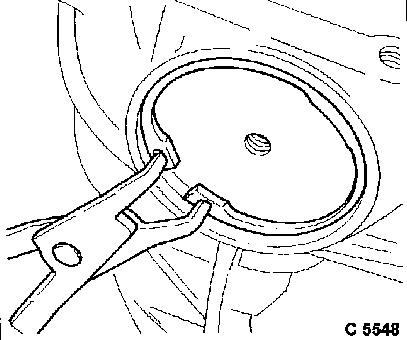
Insert 3.50 mm thick retaining ring (3) in ring gear side groove
on differential housing, ensuring that it is correctly seated.
|
|
|
|
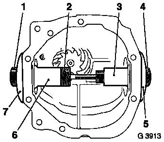
Move KM-621-6 (4) from interior of differential housing until it
is firmly seated on the retaining ring.
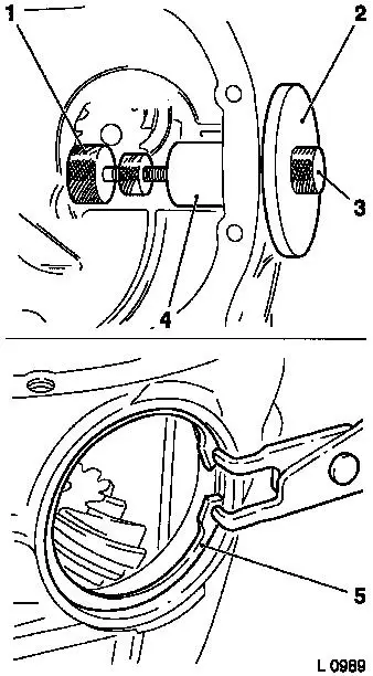
Use KM-621-6 to screw on KM-621-7 (2) and KM-621-21 (3) from the
outside. Screw KM-621-22 (1) into KM-621-6.
Insert 3.50 mm thick retaining ring (5) into groove of
differential housing on side opposite ring gear, ensuring that it
is correctly seated.
|
|
|
In accordance with the ring gear side, move KM-621-5 (6) from
interior of differential housing until it is firmly seated on the
retaining ring. Use KM-621-5 to help screw on KM-621-7 (7) and
KM-621-21 (1) from outside. Use KM-621-5 to firmly seat KM-621-22
(2) and tighten securing nut. Ensure that there is no backlash
between the tools and that the securing nut has been tightened
sufficiently, preventing any need for adjustment.
|
|
|
Remove KM-621-21 and KM-621-7, and retaining rings on both sides
of differential housing and remove special service tool
assembly.
|
|
|
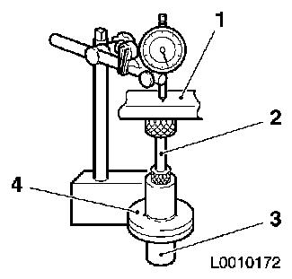
Place special tool assembly, consisting of KM-621-5 (3),
KM-621-6 (4) and KM-621-22 (2), on the guide plate. Position
KM-621-23 (1) centrally on the special tool assembly. Set dial
gauge up on KM-621-23 (1) and set to "0".
Then carefully lift probe of gauge, lay KM-621-23 (1) and
special service tool assembly aside.
|
|
|
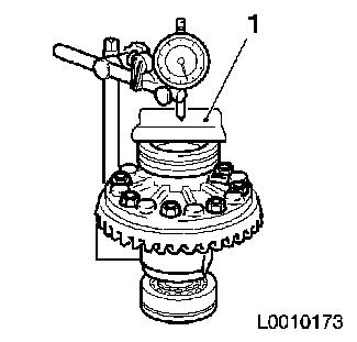
Then set up the differential with both bearing rings on the
guide plate under the dial gauge, note here the allocation of the
bearing rings to the bearings. Apply loading to the upper bearing
centrally with KM-621-23 (1) and turn differential housing a few
turns so that the bearings are seated. Assist the seating of the
bearings by pressing on KM-621-23 (1) manually. Then read off the
height difference on the dial gauge and make a note of it.
Lift probe of gauge, set KM-621-23 (1) and differential
aside.
|
|
After this, the total thickness of the two retaining rings has
to be calculated.
This is calculated from the thickness of the retaining rings
used for measuring the housing (3.50 mm + 3.50 mm = 7.00 mm), which
is added to the height difference between the special service tool
assembly and the bearing rings, calculated with the dial gauge,
plus a fixed value of 0.30 mm for the bearing pre-tension.
The value calculated in this manner represents the actual
difference between the width of the rear differential housing, the
width of the differential with bearing rings and the bearing
pre-tension. This difference is bridged by two retaining rings
whose thickness is determined by the gear tooth backlash
measurement.
To measure the gear tooth backlash, a retaining ring with 3.50
mm thickness is installed on the ring gear side of the rear
differential housing. The thickness of the other retaining ring
results from the difference calculated, from which 3.50 mm is
subtracted.
|
Sample calculation:
|
|
|
Measured difference in height between differential with bearing
rings and special service tool assembly
|
+ 0.38 mm
|
|
Thickness of retaining rings used for measurement (3.50 mm +
3.50 mm)
|
+ 7.00 mm
|
|
Bearing pre-tension
|
+ 0.30 mm
|
|
Actual difference between housing and differential
|
7.68 mm
|
|
Selection of retaining rings for tooth backlash measurement:
|
|
|
Actual difference
|
7.68 mm
|
|
Retaining ring, ring gear side
|
- 3.50 mm
|
|
Retaining ring, opposite side to ring gear
|
4.18 mm
|
|
Install
Insert differential in rear axle housing with inner bearing
rings. Lift O-ring, bearing outer ring, side opposite the ring
gear, and oil. Insert outer bearing ring on the side opposite the
ring gear. Insert retaining ring 3.50 mm thick on ring gear side,
ensure correct seating. Lift O-ring, outer bearing ring,
differential side, and oil. Place outer bearing ring on the
differential side.
|
|
|
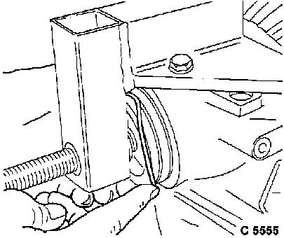
Fasten KM-621-20 (1) on differential housing. Pre-tension
differential with KM-621-20 (1) and KM-621-8 (2) and install
retaining ring with calculated thickness on opposite side from the
ring gear, ensuring correct seat. Release pre-tension.
|
|
|
Measure
|
Backlash:
|
|
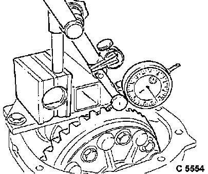
Fix gauge to rear differential housing and set as perpendicular
as possible to tooth flank of the ring gear.
|
|
Measure backlash at four different points by moving ring gear
from stop to stop.
|
The correct tooth backlash is 0.10 mm to 0.20 mm. The lower
tolerance limit is the target. A change in the tooth backlash by
0.01 mm requires a displacement of the differential by 0.016 mm
(caused by the spiral-cutting of the ring gear and drive pinion
gear). To do this, pretension differential with KM-621-20 and
KM-621-8. Remove retaining ring on ring gear side. Turn back
spindle from KM-621-20. Remove retaining ring on ring gear side and
replace with new retaining ring. Fit corresponding retaining ring
on differential side. Check tooth backlash.
|
|
|
Sample calculation:
|
|
|
|
|
Measured tooth backlash e.g.
|
|
0.30 mm
|
|
|
Target value for tooth backlash
|
-
|
0.15 mm
|
|
|
Tooth backlash to be compensated for
|
|
0.15 mm
|
|
|
|
|
|
|
|
|
|
|
|
|
Displacement factor*
|
|
1.6
|
|
|
Tooth backlash to be compensated for
|
x
|
0.15 mm
|
|
|
Displacement distance
|
|
0.24 mm
|
|
|
|
|
|
|
|
|
|
|
|
|
Final calculation of retaining rings:
|
|
|
|
|
Previous retaining ring, ring gear side
|
|
3.50 mm
|
|
|
Displacement distance
|
+
|
0.24 mm
|
|
|
New retaining ring on ring gear side
|
|
3.74 mm
|
|
|
|
|
|
|
|
|
|
|
|
|
Previous retaining ring on side opposite to ring gear
|
|
4.18 mm
|
|
|
Displacement distance
|
-
|
0.24 mm
|
|
|
New retaining ring on side opposite to ring gear
|
|
3.94 mm
|
|
|
|
|
=======
|
|
|
|
|
|
|
|
|
|
|
|
|
|
Displacement of differential
|
|
0.016 mm
|
|
|
* Displacement factor =
|
– – – – – – – –
– – – – – – – –
– -------
-
-
|
=
|
-
-
-
-
-
|
= 1.6
|
|
|
Alteration of tooth backlash
|
|
- 0.01 mm
|
===
|
|
|
|
|
|
|
|
When the backlash is correctly adjusted:
Remove
Remove retaining rings from both sides (as described), do not
mix them up.
Install
Press back bearing rings, tighten new 0-rings and coat with
special oil. Press in bearing rings and insert retaining rings (as
described), ensuring that they are correctly seated.
Remove special service tool.
|
|
|
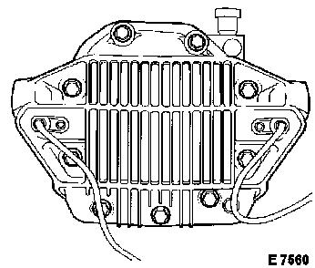
Clean sealing surfaces and coat evenly with sealing compound.
Use new Tensilock screws to mount cover on housing and tighten
fastening screws crosswise – tightening torque 60 Nm / 44.5
lbf. ft.
|
|
|
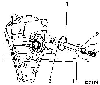
Drive in new drive shaft seal rings (3) using KM-305 (2) and
KM-621-19 (1).
Attach bracket to rear differential with new fastening bolts
– tightening torque 90 Nm / 66.5 lbf. ft., then turn
fastening bolts by a further 45° + 15°.
Remove
Remove rear differential from KM-622-A and KM-113-2.
Install
Install rear differential, see operation "Rear Differential,
Remove and Install or Replace".
|
|
|
