|
Attaching Parts from Cylinder Head, Detach and
Reattach
 Remove Remove
Remove cylinder head – see operation "Cylinder Head,
Remove and Install".
Caution
Lay cylinder head aside on wooden blocks to avoid damaging the
injection nozzles, glow plugs and valves.
|
Remove
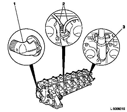
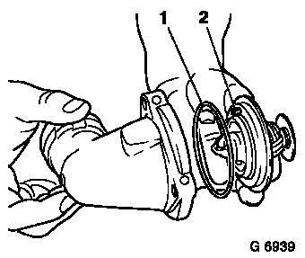
Detach thermostat housing (1) from cylinder head.
Detach oil leak lines (2) from injector nozzle holder.
Remove injection nozzle holder from cylinder head with KM-133-C
(3).
|
|
|
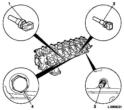
Remove sheathed glow plugs (3).
Remove temperature sensors (1) and (2) out of cylinder head.
Remove both closure plugs (4) out of cylinder head.
|
|
|
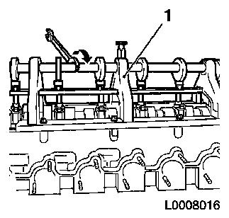
Attach Camshaft Hold Down Device KM-839 (1) to cylinder
head.
Pre-tension camshaft bearing cap by turning the eccentric shaft
of the Camshaft Hold Down Device KM-839 in direction of arrow.
Remove camshaft bearing caps evenly, working from outside to
inside.
Relieve tension in camshaft bearing cap by turning the eccentric
shaft of the Camshaft Hold Down Device KM-839 in direction of
arrow.
Remove Camshaft Hold-Down Device KM-839 from cylinder head.
Lay camshaft bearing caps aside according to cylinder
allocation.
Remove camshaft.
|
|
|
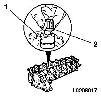
Pull out hydraulic valve lifter (1) with KM-845 (2) and lay
aside according to valve allocation – do not damage running
surfaces of hydraulic valve lifter.
|
|
Note: Check/overhaul
cylinder head – see operation "Cylinder Head and Attaching
Parts, Check and Align" and/or "Cylinder Head, Overhaul".
 Install
Insert camshaft such that the 1st cylinder cam points
upwards.
Attach camshaft bearing caps in cylinder order.
Attach Camshaft Hold Down Device KM-839 to cylinder head.
Carefully pre-tension camshaft bearing caps.
Tighten camshaft bearing caps each in steps of 1/4 turn from
inside outwards – tightening torque 15 Nm / 11 lbf. ft.
Remove
Remove Camshaft Hold-Down Device KM-839 from cylinder head.
Install
Install closure plug with new gasket in timing case –
tightening torque 9 Nm / 6 lbf. ft.
Screw both temperature sensors into cylinder head –
tightening torque 15 Nm / 11 lbf. ft.
Install sheathed glow plugs – tightening torque 22 Nm / 16
lbf. ft.
Attach injector nozzle holder with new seal ring to cylinder
head using KM-133-C – tightening torque 60 Nm / 44 lbf.
ft.
Connect leakage oil lines to injection nozzle holder.
|
Insert seal (1) into thermostat housing. Insert thermostat into
thermostat housing.
Note: Insert
thermostat bleeding valve (2) into the guide.
|
|
Install
Attach thermostat housing to cylinder head – 10 Nm / 7
lbf. ft.
|
