|
Cylinder head, assemble
Special service tools required:
Assembly tool set KM-6215, installation/removal set MKM-6086,
KM-958, KM-835-A, KM-6152, KM-6385, KM-663, KM-352
|
 Inspect
Preconditions: All components are cleaned and checked. Cylinder
head is attached to assembly device and is upside down.
 Assemble
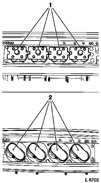
Lightly coat valve guides with oil and insert in cylinder head
in the appropriate sequence. Insert counterhold.
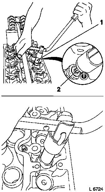
Depending on the combustion chamber design, different
counterholds (1 and 2) must be used to secure the valves.
The counterholds and fastening tools to be used can be found in
the survey .
|
|
|
 Install
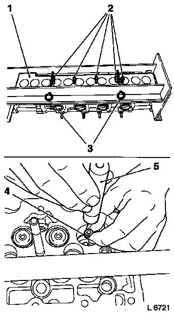
The counterhold KM-6215-2 (1) is only required for cylinder
heads with 2 valves per cylinder.
Fit counterhold KM-6215-2 (1). Attach with locking pins
KM-6215-3 (3). Turn fixing screws (2).
Turn assembly device over.
Insert lower valve spring cap / valve rotators in the
appropriate sequence.
Carefully install valve stem seals (4)
with the relevant installers (5).
|
Valve stem Ø
|
Installer
|
|
5 mm
|
KM-958
|
|
6 mm
|
KM-835-A
|
|
6 mm
|
KM-6152 (Z 22 SE)
|
|
6 mm
|
KM-6385 (Y 30 DT)
|
|
7 mm
|
KM-663
|
|
8 mm
|
KM-352
|
|
|
|
Insert valve springs and valve spring cap in cylinder head in
the appropriate sequence.
Caution
The components of the assembly head must be assembled according
to the following instructions.
Assemble
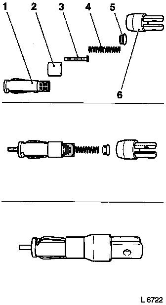
The assembly head consists of: mount (1), retaining sleeve (2),
thrust piece (3), spring (4), screw connection (5) and lever
mounting (6). The assembly head must be assembled in the above
sequence.
Different thrust pieces are used depending on engine type. The
thrust pieces to be used can be found in the survey 
The relevant sizes are stamped on the head of the thrust
pieces.
|
|
|
Caution
The combinations of support and thrust piece must always be
observed, as otherwise the valve cotters cannot be installed or the
thrust pieces are damaged.
The support and thrust piece combinations can be found in the
survey .
Assemble
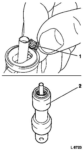
Slide retaining sleeve (2) downwards and insert valve cotters
(1) in the assembly head. Slide retaining sleeve (2) upwards, the
valve cotters are held in position.
Attach assembly head to lever MKM-6086.
|
|
|
Adjust (align) lever so that the assembly head is positioned
vertically above the valve.
Caution
To facilitate installation of the valve cotters, the assembly
head (1) should be attached to the valve stem with the thrust piece
(2). This prevents damage occurring to the thrust pieces.
Install
Press down assembly head with lever slowly and carefully until
the valve cotters engage audibly in the valve stem. Then check
seating of valve cotters.
|
|
|
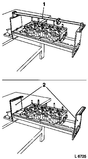
 Remove Remove
Remove lever (1) and side mounts. Remove counterhold (2) and
wooden board.
Detach cylinder head from assembly device.
 Clean Clean
After assembly of all attaching parts the cylinder head must be
cleaned thoroughly.
Install
Install attaching parts and camshaft(s) to cylinder head.
|
|
|
