|
Cylinder Head, Remove and Install
 Remove Remove
|
Remove lower engine compartment cover.
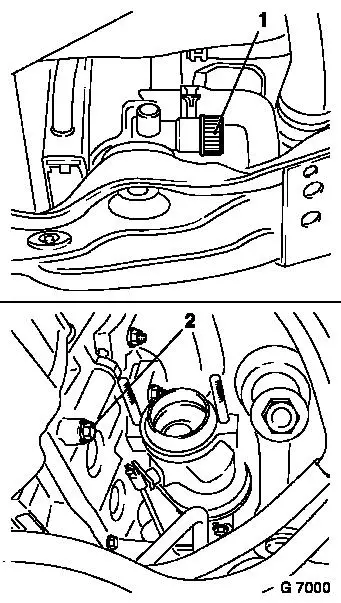
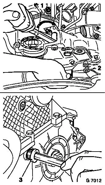
Open coolant drain plugs (1 and 2) on radiator and cylinder
block and drain coolant. Collect escaping coolant.
Drain engine oil. Collect escaping engine oil.
Remove visco-fan – see operation "Visco-fan, Remove and
Install".
Remove ribbed V-belt tensioner – see operation "Ribbed
V-belt Tensioner, Remove and Install".
Remove exhaust manifold – see operation "Exhaust Manifold,
Remove and Install".
Remove intake manifold – see operation "Intake Manifold,
Remove and Install".
|
|
|
Remove vacuum pump – see operation "Vacuum Pump, Remove
and Install".
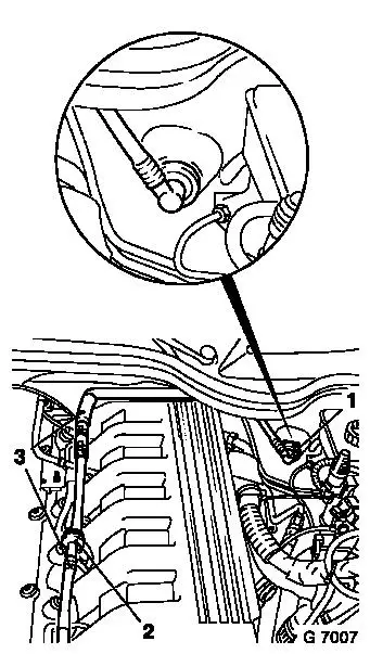
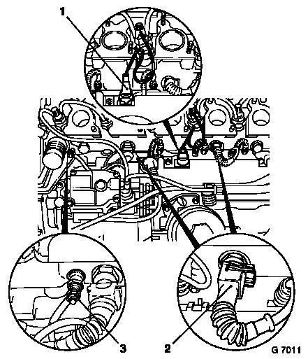
Disconnect vacuum hose (1) from brake servo.
Disconnect vacuum hoses (3) from non-return valve (2).
Remove vacuum hoses.
Detach fuel injection pump oil leak line from "1st cylinder"
injection nozzle bracket.
Remove injection lines – see operation "Injection Lines,
Remove and Install".
Disconnect metal exhaust gas recirculation pipe – see
operation "Metal Exhaust Gas Recirculation Pipe, Remove and Install
X 25 DT/25 DT" in group "L".
|
|
|
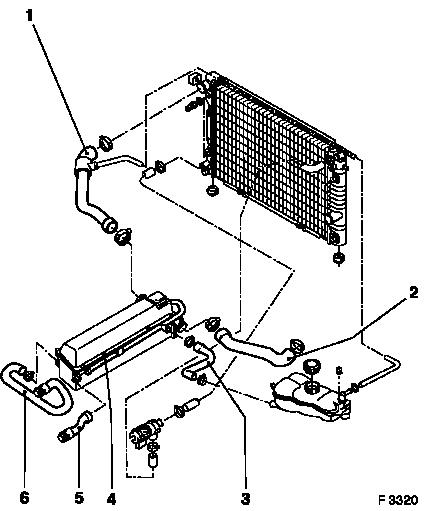
Remove coolant hoses (1) and (6) from cylinder head.
Remove coolant hose (2) from thermostat housing.
Remove coolant hoses (3) and (5) from coolant pipe.
Disconnect coolant pipe (4) (1 attachment screw).
|
|
|
Turn crankshaft in direction of engine rotation to "1st Cylinder
TDC" – see operation "Timing, Check".
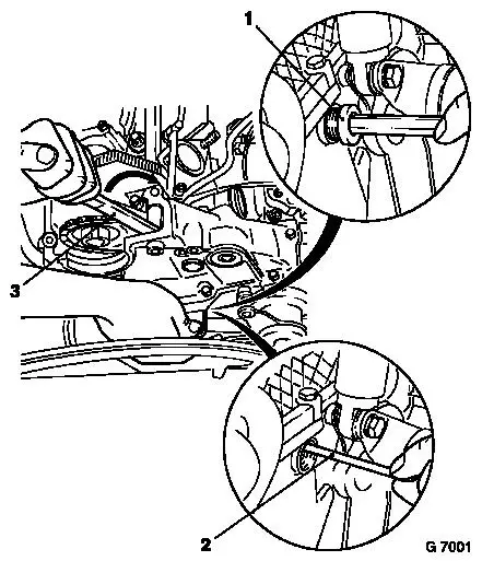
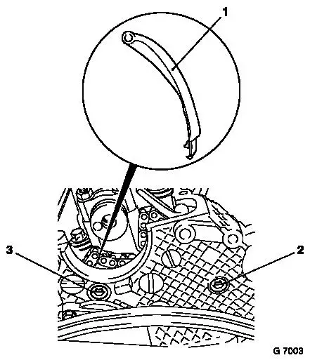
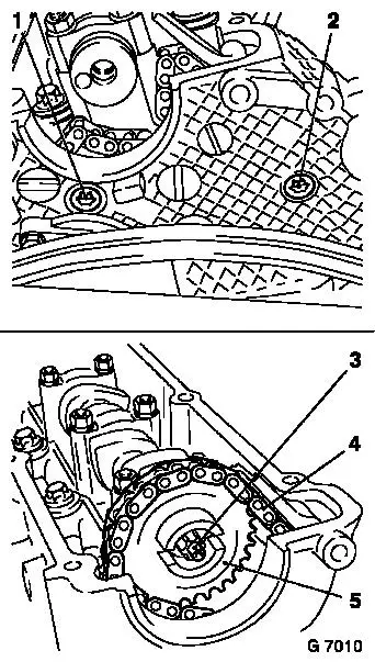
Remove closure bolt (1) from timing case.
Place Lever KM-822 (3) between upper tensioner blade and closure
bolt and tighten chain tensioner in direction of arrow, thus
slackening the timing chain.
Whilst the timing chain is slackened using Lever KM-822, insert
Retaining Pin KM-823 (2) into chain tensioner hole. This locks the
chain tensioner.
|
|
|
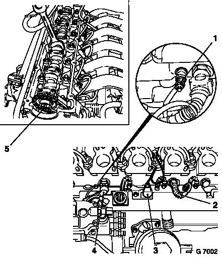
Counterhold camshaft against camshaft hex. Remove oil injection
nozzle (5) from camshaft sprocket.
Lift timing chain from camshaft sprocket and remove camshaft
sprocket from cylinder head.
Remove fastening nuts of wiring harness plug for sheathed glow
plug (1) (6 nuts).
Disconnect wiring harness plug from sheathed glow plugs.
Disconnect wiring harness plug (2) from coolant temperature
sensor.
Disconnect wiring harness plug (4) from coolant temperature
sensor.
Disconnect wiring harness plug (3) from injection nozzle needle
movement sensor.
|
|
|
Remove stud bolt (3) for upper tensioning rail (1).
Remove upper tensioning rail.
Remove stud bolt (2) for upper guide rail.
Note: When lifting
the cylinder head, ensure that the upper guide rail is not
damaged.
|
|
|
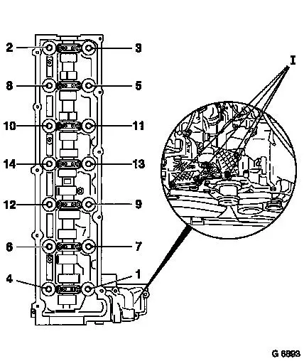
Remove
Remove fastening nuts/attachment screws (I) from timing
case.
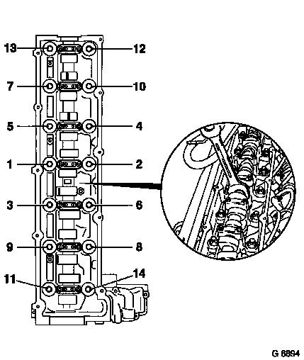
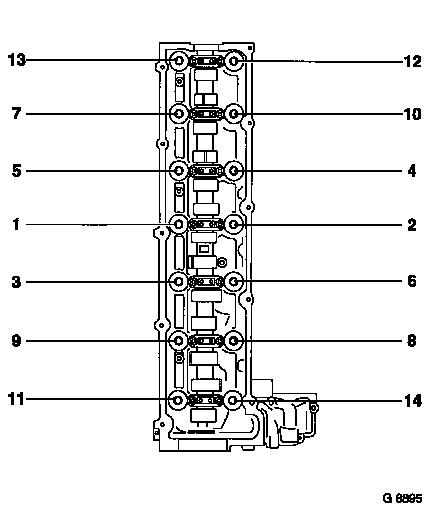
Loosen cylinder head bolts in illustrated sequence from outside
inwards by turning first 1/4 and then 1/2 revolutions and then
remove.
Lift off cylinder head and place onto wooden blocks.
Do not damage cable and attaching parts.
Note: If the cylinder
head is to be checked and/or overhauled, the outer attaching parts
must be removed from the cylinder head and then reattached –
see operation "Attaching Parts from Cylinder Head, Detach and
Reattach".
 Clean Clean
Remove seal residue, clean sealing surfaces.
Threaded holes in cylinder block must be free of dirt and
liquid. Ensure that no seal residue falls into the cylinder block
oil and coolant channels.
|
|
 Inspect
|
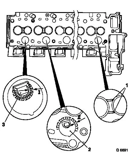
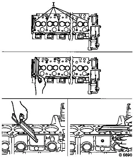
Note: When checking
the swirl chambers and web plates, the following points must be
observed:
- Radial cracks of up to 5 mm in length (dimension II) are
permissible around the swirl chambers (2).
- Radial cracks of up to 3 mm in length (dimension I) are
permissible around the swirl chambers openings (3).
- Splitting of the web plates (1) results from engine operation
and is therefore permissible.
|
|
|
Note: Height
variations are possible in the vicinity of the valves and swirl
chambers of each individual cylinder (shaded areas). Errors can
occur when performing a straight edge measurement over these areas
(e.g. diagonal measurement) – this method is therefore no
longer permissible.
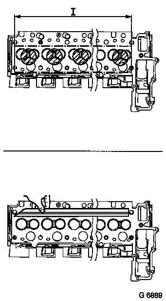
Inspect
The measurement of longitudinal
deformation of the cylinder head should be made along the dash-dot
line shown in the illustration (dimension I) – use straight
edge and feeler gauge:
|
max. longitudinal deformation:
|
0.10 mm.
|
|
|
|
The measurement of lateral deformation of the cylinder head
should be made along the dash-dot lines shown in the illustration
(dimension I) – use straight edge and feeler gauge:
|
max. lateral deformation:
|
0.05 mm.
|
Check length and width of cylinder block sealing surfaces for
deformation and diagonals for warpage – use straight edge and
feeler gauge. Permissible deviation in flatness and warpage:
|
Cylinder block max.
|
0.02 mm
|
|
|
 Measure
|
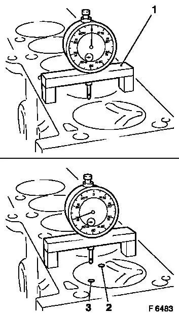
Place Measuring Bridge KM-301 (1) with Gauge MKM-571-B on
cleaned sealing surface of cylinder block and set dial pointer to
"0" under pretension.
Place Measuring Bridge KM-301 (1) and Gauge MKM-571-B onto
cleaned pistons and measure highest point by turning crankshaft.
Piston projection is measured at positions (2) and (3) on each
piston. Perform this measurement on all 6 pistons. The largest
value is the piston projection value.
|
|
|
Inspect
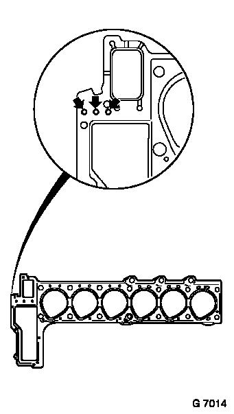
Permissible piston projection: 0.54 to 0.99 mm.
Note: The 3 hole
cylinder head gasket (arrows) can only be used if the permissible
piston projection has been reached.
Check centring sleeves for damage and correct installation
positions.
|
|
 Install
|
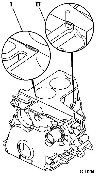
Apply adhesive sealing compound (white) to separating points I +
II (engine block / timing case) (observe specification).
Note: Cylinder head
and seal should be installed within half an hour.
Caution
The sealant should be applied as in
the diagram:
|
I
|
Bead:
|
approx.
|
10 mm long
|
|
|
|
|
1 – 2 mm high
|
|
|
|
approx.
|
3 mm wide
|
|
II
|
Bead:
|
approx.
|
7 mm long
|
|
|
|
|
1 – 2 mm high
|
|
|
|
approx.
|
3 mm wide
|
Fit new cylinder head gasket.
|
|
|
Turn camshaft at hex of the camshaft until the cams of the 1st
cylinder point upwards.
Ensure that the upper guide rail is not damaged when putting on
the cylinder head.
Lead timing chain through cylinder head.
Put on cylinder head and attach in shown order using new, oiled
cylinder head screws, working from inside to outside.
Note: Observe
"General Repair Instructions".
|
|
Torque/angle method
|
Cylinder head to cylinder block
|
Nm
|
|
1.
|
Tightening torque
|
80
|
|
2.
|
Loosen all bolts 180°
|
|
|
3.
|
Tightening torque
|
50
|
|
4.
|
Torque-angle method
|
90° to 100°
|
|
5.
|
Torque-angle method
|
90° to 100°
|
|
6.
|
Torque-angle method (after 25 minutes of warm running phase)
|
90° to 100°
|
|
Install
Connect fastening nuts and attachment screws to timing case
– tightening torque 9 Nm / 6.5 lbf. ft.
Insert timing chain upper tensioner blade. Ensure that timing
chain upper tensioner blade is correctly seated.
Note: Always replace
oil injection nozzle.
Install
Install stud bolt (1) for upper timing chain tensioning rail and
stud bolt (2) for upper timing chain guide rail with surface
sealant (green) – tightening torque 9 Nm / 6.5 lbf. ft.
Insert camshaft sprocket (5) into cylinder head, lie timing
chain (4) on the camshaft sprocket and attach the camshaft sprocket
to the camshaft with a new oil spray nozzle (3) – ensure that
timing chain is seated correctly on the camshaft sprocket.
|
|
|
Connect wiring harness connector (3) and new fastening nuts to
sheathed glow plugs (6 nuts) – tightening torque 5 Nm / 4
lbf. ft.
Connect wiring harness connector (2) to coolant temperature
sensor.
Connect wiring harness connector (2) to coolant temperature
sensor.
Connect wiring harness connector (1) to injection nozzle needle
movement sensor.
|
|
|
Place Lever KM-822 (1) between upper timing chain tensioner
blade and closure bolt and push back the chain tensioner in the
direction of the arrow. The chain tensioner is slackened and the
Retaining Pin KM-823 (2) can be taken out of the hole.
Install screw plug (3) and new seal into timing case –
tightening torque 9 Nm / 6.5 lbf. ft.
Adjust timing – see operation "Timing, Check".
Install exhaust gas recirculation metal pipe – see
operation "Exhaust Gas Recirculation Metal Pipe, Remove and Install
X 25 DT / 25 DT" in group "L".
Connect oil leakage line between injection pump and "1st
cylinder" injection nozzle holder.
Connect injection lines to injection nozzle holders and
injection pump with KM-812 – tightening torque 25 Nm / 18
lbf. ft.
|
|
|
Install coolant hoses free of oil and grease.
Connect coolant hoses/coolant pipe (1 to 6).
Install vacuum pump – see operation "Vacuum Pump, Remove
and Install".
Install intake manifold – see operation "Intake Manifold,
Remove and Install".
Install exhaust manifold – see operation "Exhaust
Manifold, Remove and Install".
Install ribbed V-belt tensioner – see operation "Ribbed
V-belt Tensioner, Remove and Install".
Install visco-fan – see operation "Visco-fan, Remove and
Install".
|
|
Connect vacuum hoses to non-return valve.
Connect vacuum hose to brake
servo.
|
Attach oil drain plug and new oil seal to oil pan –
|
|
Tightening torque:
|
M12 x 1.5:
|
25 Nm / 18 lbf. ft.
|
|
|
|
M16 x 1.5:
|
45 Nm / 33 lbf. ft.
|
|
Top up with specified volume of engine oil.
Connect coolant drain plug and new seal to engine block –
tightening torque 40 Nm / 29.5 lbf. ft.
Close coolant drain bolt on radiator.
Install lower engine compartment cover - tightening torque 5
Nm.
Top up cooling system – see operations "Cooling System,
Top Up and Bleed" and "Cooling System, Check for Leaks".
Allow engine to warm up for 25 minutes.
Remove
|
Remove cylinder head cover – see operation "Cylinder Head
Cover, Remove and Install".
Install
Tighten cylinder head in shown sequence, working from inside to
outside – angle method 90° to 100°.
Install cylinder head cover – see operation "Cylinder Head
Cover, Remove and Install".
Inspect
Check engine oil level and correct if necessary.
|
|
|
