vauxhall Workshop Repair Guides

Vauxhall Workshop Service and Repair Manuals

Valves, remove > < Cylinder head, attach to assembly tool set KM-6215

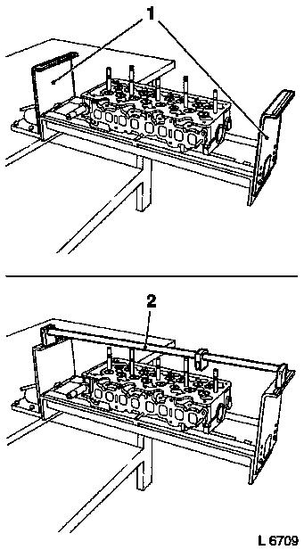
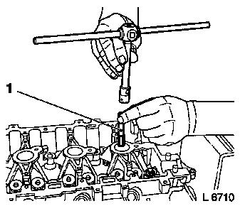
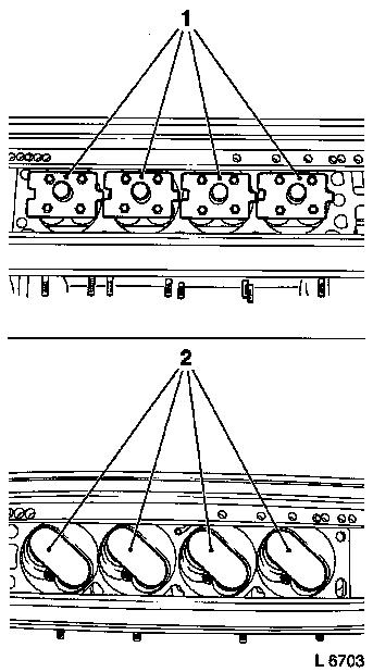
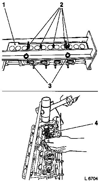
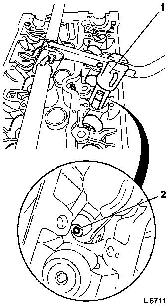
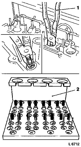
Cylinder head, disassemble

Special service tools required:

Assembly tool set KM-6215, adapter set KM-6167, valve cotter installation/removal set MKM-6086

  Disassemble

Fit side mounts KM-6215-5 (1) for KM-6215-4 (2) to assembly device. The corresponding attachment points for KM-6215-5 (1) can be found in the survey.

Attach KM-6215-4 (2).

Object Number: 2418498  Size: DEFAULT

  Clean

The spark plug threads must be cleaned of combustion residues to ensure that the counterhold can be attached correctly. Insert tap M14 x 1.25 (1) in the spark plug thread and screw in evenly.

Object Number: 2418499  Size: DEFAULT

  Install

Turn cylinder head base plate.

Depending on the combustion chamber design, different counterholds (1 and 2) must be used to secure the valves. Insert counterhold.

The counterholds and fastening tools to be used can be found in the survey.

Object Number: 2418492  Size: DEFAULT

  Remove

The counterhold KM-6215-2 (1) is only required for cylinder heads with 2 valves per cylinder.

Fit counterhold KM-6215-2 (1). Attach with locking pins KM-6215-3 (3). Turn fixing screws (2).

Turn cylinder head base plate again.

  Disassemble

Release the valve spring caps using KM-6171 (4) to ensure that no special service tools are damaged during the subsequent removal of the valve cotters. Place KM-6171 on valve spring caps and release all valve spring caps by striking them using a rubber mallet (settling behaviour).

Object Number: 2418493  Size: DEFAULT

Caution

The valve-spring compressor (1) must be positioned parallel onto the valve spring cap to ensure that neither tools nor components are damaged. Select the appropriate bore in the lever for this purpose. If the valve-spring compressor cannot be positioned parallel, the lever must be adjusted accordingly.

  Remove

Push valve-spring compressor (1) down with lever until the valve spring cap is released. Remove valve cotters (2).

Object Number: 2418500  Size: DEFAULT

Remove upper valve spring cap and valve springs and place on KM-849 (2) in sequence.

Release valve stem seals by turning with KM-840 (1) and remove from the valve guides.

Remove lower valve spring caps or valve rotators from cylinder head and also place on KM-849 (2).

Disassemble lever.

Turn cylinder head base plate. Remove wooden board KM-6215-2 and counterhold if attached.

Remove all valves and place on KM-849 (2) in sequence.

Object Number: 2418501  Size: DEFAULT

Valves, remove > < Cylinder head, attach to assembly tool set KM-6215