|
Engine, Remove and Install
The operation "Engine, Remove and Install" is described for a Z
22 XE engine with automatic transmission and LHD. Proceed
analogously for other engine and equipment versions.
Cable ties detached for removal of the engine must be reattached
at the same location on installation.
Turn steering wheel to straight-ahead position, remove ignition
key and allow steering lock to engage.
|
 Remove Remove
In vehicles with AC: Drain AC – see operation "AC, Drain"
in group "D".
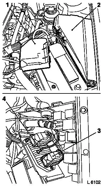
Disconnect ground cable from ground terminal and ground terminal
from battery. Unclip ground cable from battery attachment (2
clips). Detach fuse carrier (1) from relay frame. Positive cable
from positive terminal and positive terminal from battery.
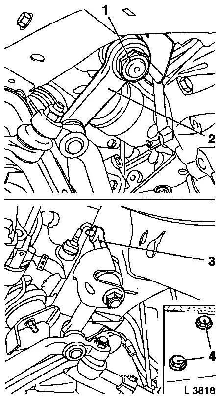
Open cover for relay frame (2). Release wiring harness plug (3)
and detach from engine control unit. Remove ground cable (4) from
engine control unit.
|
|
|
Remove positive cable (2) from rubber grommet of relay
frame.
Remove engine wiring harness with rubber grommet from relay
frame and lay aside on engine.
Disconnect multiplug (1) (twist lock). Lay wiring harness aside
on engine.
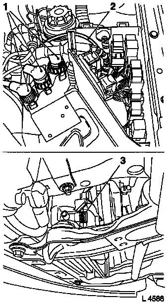
Detach lower engine cover.
Open coolant drain bolt (3) – collect coolant. Close
coolant drain bolt.
|
|
|
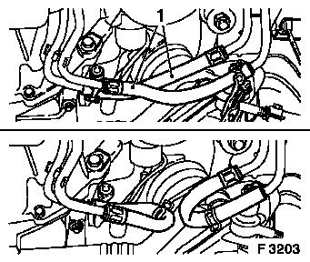
Remove upper coolant hose (1) from thermostat housing.
Detach high pressure line (2) from power steering pump –
collect hydraulic fluid.
Detach intake line (3) from power steering fluid reservoir.
|
|
|
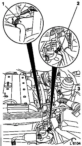
Detach vacuum line (1) from brake servo vacuum line (2) and
brake servo vacuum line from brake servo.
For vehicles with air conditioning: Push back rubber covers from
refrigerant lines (3) and (4). Detach refrigerant lines with
KM-917.
|
|
|
For version with manual transmission: Top up brake fluid
reservoir completely and close off with dummy plug.
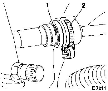
Open retaining strap (2) for connecting piece on bulkhead.
Detach retaining clip (1) and disconnect clutch actuation
pressure line. Reinsert retaining clip.
|
|
|
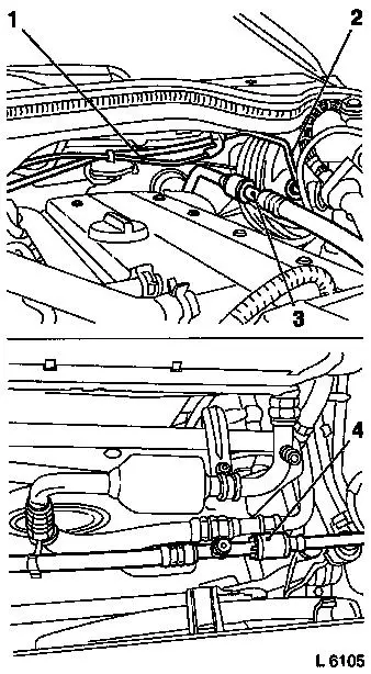
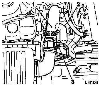
Disconnect wiring harness plug (3) from hot film mass air
flowmeter.
Disconnect crankcase ventilation hose (2) from cylinder head
cover.
Detach air intake hose (1) with hot film mass air flowmeter from
upper part of air cleaner housing and throttle body.
Detach coolant hoses from compensation tank.
Caution
Fuel leak – observe safety regulations and national
legislation. Reduce fuel pressure with Pressure Tester
KM-J-34730-91 via testing port – collect escaping fuel in
suitable container.
Remove
Detach fuel lines from fuel distributor pipe.
|
|
|
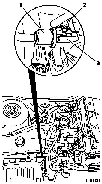
Detach wiring harness plug (2) from tank vent valve (1).
Detach tank vent valve hose (3) from tank vent valve.
Note: When detaching
the tank vent valve hose, ensure that the valve connection is not
damaged. Damaged valves must be replaced.
Caution
Damaged valve supports can cause a vehicle fire as a result of
leaks.
|
|
Remove
|
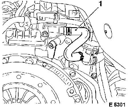
Detach coolant hoses from coolant pipe and heat exchanger.
Detach coolant hose (1) from coolant flange.
Remove front wheels.
Remove fastening nuts for tie rods from steering knuckle. Detach
tie rods from steering knuckle with KM-507-C.
|
|
|
Remove fastening nut on steering arm (1).
Press out steering arm (2) with KM-146-01.
Remove fastening bolts (4) from idler bracket (3).
|
|
|
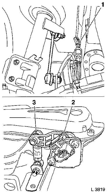
For vehicles with xenon headlamp: Disconnect wiring harness plug
from vehicle level control sensor (2). Remove ball head (3) from
vehicle level control sensor.
Detach fastening nuts for link rod (1) on both sides from
stabiliser – counterhold with open-ended spanner at the
flattened surfaces.
|
|
|
Detach fastening nuts (1) and remove fastening bolts.
Pull guide joints (2) downwards out of steering knuckle.
Disconnect wiring harness plug for oxygen sensor. Remove front
exhaust pipe.
|
|
|
Disconnect transmission fluid lines (1) and connect to each
other – collect escaping transmission fluid.
|
|
|
Detach selector lever linkage (2).
Remove propshaft (1) from transmission.
For version with manual transmission: Remove propshaft –
see operation "Propshaft, Remove and Install or Replace" in group
"F".
|
|
|
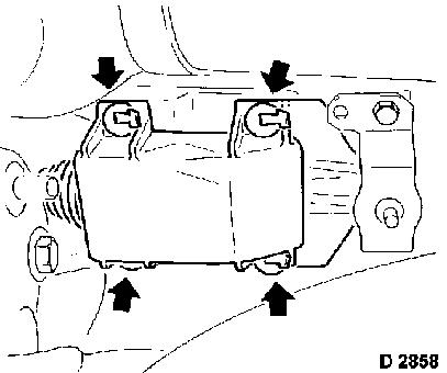
For version with manual transmission: Remove 4 clips (arrows)
from cover on shift outrigger.
Push cover forwards.
|
|
|
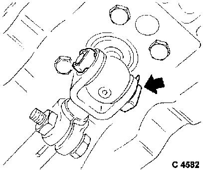
Detach retainer (arrow) from pin.
Pull pin out from shift rod and fork.
|
|
|
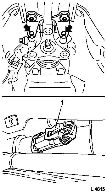
For version with manual transmission: Remove fastening bolts
(arrow) from shift outrigger.
Disconnect AC compressor wiring harness plug (1).
|
|
|
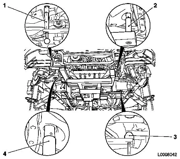
Install Base Frame KM-904 with Centring Mount KM-6190 on
hydraulic jack and position without play under front axle body
– ensure that the centring pins (2) and (4) sit in the
corresponding mounts of the front axle body (use hydraulic jack
which can be lowered to at least 100 cm).
Caution
Removal of the front axle body with an impulse or impact
screwdriver is not permissible. Note various lengths of bolts.
Note: Before removing
the engine, the split pins of the centring pins (1) and (3) must be
pulled out so that the centring pins cannot engage in the
corresponding bores.
|
|
Remove
|
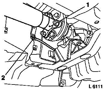
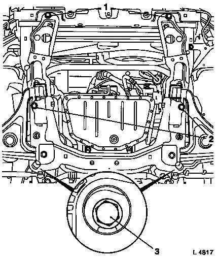
Unscrew transmission holder from underbody.
Remove front fastening bolts (1), centre fastening bolts (2) and
rear fastening bolts (3).
Carefully lower front axle body with engine and transmission
– ensure that no attaching parts are damaged.
Lower hydraulic jack completely.
Caution
Ensure the threads of the captive nuts move freely before
installing front axle body and transmission, replace captive nuts
if necessary.
|
|
 Install
|
Carefully guide front axle body with engine and transmission
into engine compartment and lift until the drive unit is positioned
free of play on the chassis – ensure that the centring pins
of KM-6190 are seated in the corresponding mounts and no attaching
parts are damaged.
Note: Before
installing the engine, the centring pins (1) and (3) must be pushed
up and secured with the corresponding split pins.
When moving in the engine, ensure that centring pins (1), (2),
(3) and (4) engage in the corresponding mounts of the front axle
body / underbody.
|
|
|
Insert new fastening bolts for front axle body to front member
and side member.
Tighten fastening bolts for front of front axle body (1) to
front member – tightening torque 65 Nm / 48 lbf. ft. +
30° + 15°.
Tighten fastening bolts (2) for centre of front axle body to
side member – tightening torque 150 Nm / 111 lbf. ft. +
30° + 15°.
Tighten fastening bolts (3) for rear of front axle body to side
member – tightening torque 130 Nm / 96 lbf. ft. + 30° +
15°.
|
|
Attach transmission holder to underbody – tightening
torque 45 Nm / 33 lbf. ft. 1)
.
Lower hydraulic jack with KM-904 and KM-6190 and remove.
Connect wiring harness plug for air conditioning compressor.
For version with manual transmission: Attach shift outrigger.
Attach shift fork to shift rod. Secure shift outrigger cover.
Attach propshaft – see operation "Propshaft, Remove and
Install or Replace" in group "F".
Attach propshaft to transmission – tightening torque 95 Nm
/ 70 lbf. ft.
Connect selector lever linkage.
Attach transmission fluid line with new seal rings to
transmission – tightening torque 25 Nm / 18.5 lbf. ft.
Attach transmission fluid line to transmission with union nut
– tightening torque 30 Nm / 22 lbf. ft.
Attach idler bracket to body – tightening torque 55 Nm /
41 lbf. ft. + 75° + 15° 1)
.
Attach steering arm to steering shaft with new fastening nut
– tightening torque 160 Nm / 118 lbf. ft.
Connect tie rods to steering knuckle with new fastening nuts
– tightening torque 60 Nm / 44 lbf. ft.
|
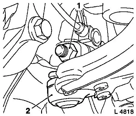
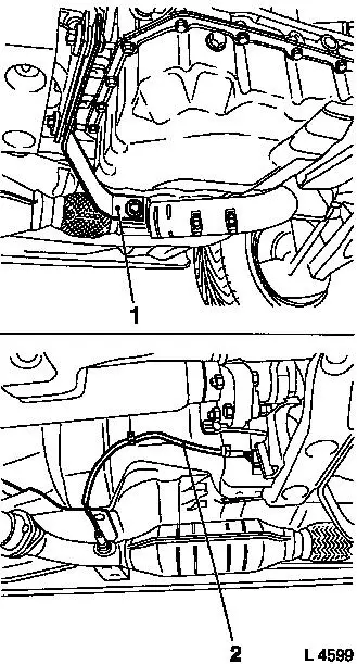
Attach front exhaust pipe to bracket (1) and to exhaust manifold
with new gasket – tightening torque 25 Nm / 18.4 lbf. ft. 2) .
Attach front exhaust pipe to centre exhaust pipe –
tightening torque – 18 Nm / 13 lbf. ft.
Route oxygen sensor wiring harness (2). Disconnect wiring
harness plug for oxygen sensor.
|
|
Connect guide joints to steering knuckle – tightening
torque 100 Nm / 74 lbf. ft.
Attach link rods to stabiliser with new fastening nut –
tightening torque 65 Nm / 48 lbf. ft.
For vehicles with xenon low beam headlamps: Attach ball head and
wiring harness plug to vehicle level control.
Attach front wheel – tightening torque 110 Nm / 81 lbf.
ft.
Detach lower engine cover.
Attach coolant hoses to coolant pipe, heat exchanger and coolant
flange.
Attach tank vent valve wiring harness and hose to tank vent
valve.
Attach fuel lines to fuel distributor pipe – tightening
torque 15 Nm / 11 lbf. ft.
Attach coolant hoses to compensation tank.
Attach air intake hose with hot film mass air flowmeter to upper
part of air cleaner housing and to throttle body. Attach crankcase
vent hose to cylinder head cover. Connect wiring harness plug to
hot film mass air flowmeter.
For version with manual transmission: Connect clutch actuation
pressure line and close retaining strap.
For vehicles with air conditioning: Connect refrigerant lines
and slide on rubber covers.
Attach vacuum line to brake servo vacuum line and brake servo
vacuum line to brake servo.
Attach high pressure line to power steering pump –
tightening torque 28 Nm / 20.5 lbf. ft. Attach power steering
vacuum line to power steering fluid reservoir.
Attach upper coolant hose to thermostat housing.
Route engine wiring harness and connect multiplug (twist
lock).
Insert engine wiring harness with rubber grommet into relay
frame. Attach wiring harness plugs to engine control unit and lock.
Secure ground cable to engine control unit. Insert positive cable
into rubber grommet and secure to positive terminal. Close relay
frame cover.
Attach ground cable to ground terminal.
Connect battery and install fuse carrier in relay box.
 Inspect
Charge cooling system – see operation "Cooling System,
Charge and Bleed" and "Cooling System, Check for Leaks".
For version with manual transmission: Bleed clutch actuation
– see operation "Hydraulic Clutch Actuation, Bleed" in group
"K".
Charge power steering hydraulic system – see operation
"Hydraulic System Charge and Bleed" in group "M".
Charge air conditioning – see operation "Air Conditioning,
Evacuate and Charge" in group "D".
1 ) Clean thread and insert bolts with bolt locking
compound (red).
2 ) Use new nuts.
|
