|
Inner diameter of valve guide, check
Preconditions: Valves removed.
Special service tools required:
MKM-6216, MKM-6216-200/300/400
Note: The
engine-specific values can be found in the corresponding "Technical
Data".
|
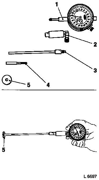
The components of the dial gauge must be assembled according to
the following instructions.
 Assemble
Insert extension (3) in holder (2) and fasten. Insert internal
caliper (4) in extension and fasten. Attach holder with extension
and internal caliper to the dial gauge (1) with approx. 1 mm
pretension and fasten. Fit calibration disc (5) for adjusting the
dial gauge onto the internal caliper. Adjust dial gauge to Zero by
turning dial. Carefully remove calibration disc.
|
|
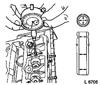
 Measure
|
Determine inner diameter of valve guide at three different
levels, note values. Calculate mean value.
Calculation example:
Inner diameter of valve guide:
|
Measurement I
|
7.025 mm
|
|
|
|
Measurement II
|
7.030 mm
|
|
|
|
Measurement III
|
7.020 mm
|
|
|
|
|
21.075 mm
|
: 3 =
|
7.025 mm
|
|
|
|
|
|
Mean value = 7.025
|
|
|
