Part Locations
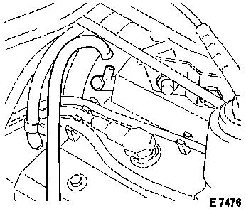
The
coordinate system shows the locations of the control unit, fuses and wiring
harness plugs which are required for checking the central door locking system.
|
Parts
|
|
Coordinates
|
Installation
position
|
| |
|
|
|
|
|
|
|
|
|
LHD
|
RHD
|
|
|
| |
|
|
|
|
|
|
| Control
unit |
|
|
|
|
|
|
|
K37
|
Central
locking control unit
|
F 3 H
|
F 3 H
|
Behind
front right footwell panelling
|
|
| |
|
|
|
|
|
|
| Fuses |
|
|
|
|
|
|
| F1
- F35 |
|
Fuses
|
B 3 H
|
E 3 H
|
Fuse
box
|
|
| |
|
|
|
|
|
|
| Wiring
harness plug |
|
|
|
|
|
|
| X1 |
|
Instrument
panel/body, 107-pin
|
A 3 G
|
A 3 G
|
Behind
front left footwell panelling
|
|
| X11 |
|
Body/driver's
door, 30-pin
|
A 3 H
|
F 3 H
|
A
pillar, driver's side
|
|
| X12 |
|
Body/co-driver's
door, 30-pin
|
F 3 H
|
A 3 H
|
A
pillar, co-driver's side
|
|
| X13 |
|
Body/rear
left door, 15-pin
|
A 4 H
|
A 4 H
|
B
pillar, left
|
|
| X14 |
|
Body/rear
right door, 15-pin
|
F 4 H
|
F 4 H
|
B
pillar, right
|
|
| X22 |
|
Body/luggage
compartment lid, 9-pin
|
B 7 J
|
B 7 J
|
Luggage
compartment, behind left rear quarter panelling
|
|
| X23 |
|
Body/tailgate,
9-pin
|
B 7 K
|
B 7 K
|
Luggage
compartment, behind left rear quarter panelling
|
|
| XD |
|
Diagnosis,
16-pin
|
B 3 H
|
E 3 H
|
Relay
box, inside
|
|
|
|
|
|
|
|
|
|