
Vectra B
Field Remedy: 1400
Remedy:
I:   Preparation of an A-pillar check link carrier and an A-pillar
     inner reinforcement plate.
II:  Replacement of the A-pillar check link carrier.
III: Repair of the crack in the A-pillar.
Note:
For each A-pillar check link carrier repair side is required:
1 A-pillar check link carrier - left side 1 A-pillar check link carrier - right side 4 Fixing screws 4 Fixing nuts
     The A-pillar reinforcement plate must be made from the A-pillar
     carrier of the respective other side.
Working procedure: I: Preparation of an A-pillar check link carrier and an A-pillar inner reinforcement plate Important:
     When preparing the A-pillar check link carrier and the
     A-pillar inner reinforcement plate, the dimensions must be
     meticulously kept and the bores must be made exactly; otherwise,
     problems may arise during the installation of the check link to
     the A-pillar check link carrier.
 1. Scribe the A-pillar check link carrier (dimension "I" 7 mm,
    dimension "II" 8 mm, dimension "III" 6,5 mm) and punch it
    (picture I).
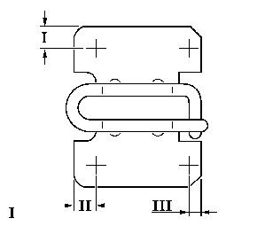
 2. Predrill the A-pillar check link carrier 4 times (diameter 3 mm).
 3. Rebore the A-pillar check link carrier 4 times (diameter 6,5 mm).
 4. Debur the bores.
 5. Align the A-pillar check link carrier and the A-pillar inner
    reinforcement plate to each other (the A-pillar check link
    carrier serves as drill template).
 6. Mount the A-pillar check link carrier and an A-pillar inner
    reinforcement plate into the vice of the stationary drilling
    machine.
 7. Drill the A-pillar inner reinforcement plate through the A-pillar
    check link plate (diameter 6.5 mm).
 8. Debur the bores.
 9. Remove the surface-coating in the welding area of the A-pillar
    inner reinforcement plate with emery cloth or a file.
10. Remove the surface-coating in the welding area of the fixing nuts
    with emery cloth or a file.
11. Mount the A-pillar check link carrier and the A-pillar inner
    reinforcement plate with fixing screws and fixing nuts, join these
    by screwing hand-tight.
Note:
     Locate the fixing nuts on the side of the A-pillar inner
     reinforcement plate.
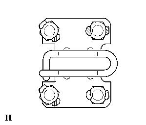
12. Fix the fixing nuts with two welding points each to the A-pillar
    inner reinforcement plate (picture II).
13. Remove the fixing screws. II: Replacement of the A-pillar check link carrier Note:
     Be aware of the mounting position of the A-pillar check link
     carrier:
     The big bore points upwards.
     Be aware of the mounting position of the A-pillar inner
     reinforcement plate:
     The big bore points upwards.
1. Remove front door
     - see working procedure "Front Door or Rear Door, Detach and
       Reattach (Modells F35, F19, F68)", group "A", Service
       Instruction Vectra-B.
2. Remove the A-pillar lower interior lining
     - see working procedure "Inner Panelling - Lower A-Pillar,
       Remove and Install", group "C", Service Instruction
       Vectra-B.
3. Remove existing control units from the lower A-pillar.
4. Expose and unplug existing wiring harness connectors.
5. Fold back the carpet.
6. Fold back the legroom insulation.
7. Protect carpet and legroom insulation against contamination
and flying sparks.
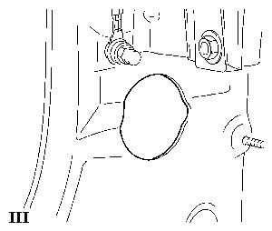
8. Drill access aperture (diameter 51 mm) to the inner A-pillar
with a circular hole drilling machine (picture III).
9. Debur the bore.
10. Remove drill chips completely.
11. Remove the front door sealing in the A-pillar area.
12. Scribe the position of the A-pillar check link carrier on the
A-pillar.
13. Drill out the 6 welding points of the A-pillar check link
carrier with a welding point drill.
14. Remove the A-pillar check link carrier.
15. If necessary, adjust or repair the A-pillar (A-pillar repair see
working procedure "III").
16. Grind the A-pillar naked in the area of the A-pillar check link
carrier using an angle grinder.
17. Install the front door.
18. Install a new A-pillar check link carrier to the check link.
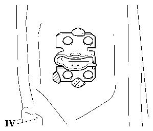
19. Determine the position of the A-pillar check link carrier and
fix the A-pillar check link carrier with three welding points to
the A-pillar (prior to this, grind the welding areas of the
A-pillar check link carrier naked) (picture IV).
20. Remove front door.
21. Drill 4 bores into the A-pillar through the A-pillar check link
carrier (diameter 6.5 mm).
22. Grind the welding points off the A-pillar check link carrier.
23. Remove the A-pillar check link carrier.
24. Debur the bores.
25. Paint the A-pillar, the A-pillar check link carrier and the
A-pillar inner reinforcement plate.
26. Fix retaining band to the A-pillar inner reinforcement plate (in
order to avoid rattling noise, do not use welding wire or cables).
27. Insert the A-pillar inner reinforcement plate, through the
opening of the A-pillar.
28. Install the A-pillar check link carrier to the A-pillar using
new fixing screws – tightening torque 10 Nm (use locking
compound).
29. Cut off as much of the retaining band as possible.
30. Prepare a repair sheet "lateral bulkhead" for closing the bore
in the inner A-pillar.
31. Cut off the bonnet release holder from the repair sheet "lateral
bulkhead".
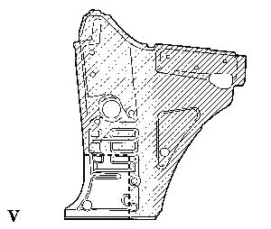
32. Scribe and cut the repair sheet "lateral bulkhead" (picture V).
33. Scribe and cut the repair sheet "lateral bulkhead" (picture VI). 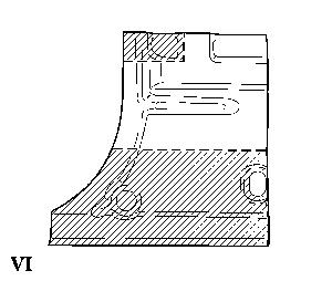
34. Scribe and cut the repair sheet "lateral bulkhead" (picture VII). 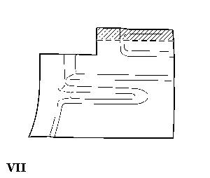
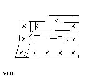
35. Scribe the drill points for the welding points on the repair sheet
    (figure VIII).
36. Drill the scribed welding points into the repair sheet
(diameter 6 mm).
37. Debur the bores.
38. Hold the repair sheet in the legroom to the inner A-pillar and
scribe the bores as well as the shape of the repair sheet to the
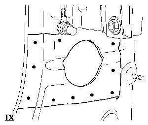
inner A-pillar (picture IX).
39. Take the repair sheet off.
40. Protect the dashboard, the seats and the carpet against flying
    sparks.
41. Grind the inner A-pillar naked in the area of the scribed welding
    points.
42. Attach the repair sheet to the inner A-pillar and fix it with two
    grip clamps.
Caution:
     During welding work, an assistant must be present, carrying a
     fire extinguisher. The welding process must be observed through
     the opening of the front door wiring harness in the A-pillar.
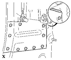
43. Weld the inner A-pillar repair sheet in the legroom (do not weld
    seams, let welding points cool down) (picture X).
44. Grind the welding points in the area of the front door sealing.
45. Apply corrosion protection to the inner A-pillar with a brush.
46. Apply cavity protection to the inner A-pillar.
47. Install the inner and outer front door wiring harness sealing
    to the A-pillar.
Note:
Observe the mounting position – the arrow must point upwards.
48. Unfold the legroom insulation.
49. Unfold the carpet.
50. Plug in existing wiring harness connectors and fix them to the
    A-pillar.
51. Install existing control units to the A-pillar.
52. Install the A-pillar lower interior lining
     - see working procedure "Inner Panelling - Lower A-Pillar,
       Remove and Install", group "C", Service Instruction Vectra-B.
53. Install front door
    - see working procedure "Front Door or Rear Door, Detach and
      Reattach (Modells F35, F19, F68)", group "A", Service
      Instruction Vectra-B.
III: Repair of the crack in the A-pillar 1. Bore through the ends of the crack (diameter 2.5 mm). 2. Weld the crack and the bores. 3. Grind the repaired area. Parts: Part-No.: Catalog-No.: 1 A-pillar check link carrier - 90568535 90 01 095 left side 1 A-pillar check link carrier - 90568536 90 01 094 right side 4 Fixing screws 11093871 20 35 600 4 Fixing nuts 11011418 20 64 155 Panel, Dash Side, LH 90568027 01 02 708 Panel, Dash Side, RH 90568028 01 02 710 Labour Times: TC: Hours:
T 8 140 00    Repair of A-pillar       90          5.8
              check link carrier
T 8 140 01    Paint and finish         90          2.6
              works
The costs for this repair will be covered for vehicles not older
than 3 years and a mileage lower than 100.000 km.
The regular warranty procedure should be used for claiming
Set-up-time.
|
||||||||||||||||||||