Engine, Remove and Install Notice: The operation is described for a vehicle with air conditioning, for vehicles without air conditioning proceed analogously.
 Remove, Disconnect Remove, Disconnect Drain air conditioning - see operation "Air Conditioning, Drain" in group "D". Remove engine cover. For X 20 DTL: Remove radiator cover. Up to MY '98: Disconnect wiring harness plug from intake air temperature sensor (1). Disconnect wiring harness plug (2) from hot film mass air flow meter. Detach engine vent hose (3) from cylinder head cover and detach air intake hose (4) from turbocharger. As of MY '98: Detach relay box from air filter housing and place to one side. Remove air cleaner housing (5) with air intake hose - see illustration "Air Cleaner Housing, Air Duct". | 
|
Remove, Disconnect For X 20 DTL: Detach charge air hose (2) from charge air pipe and upper part of intake manifold. For X 20 DTH: Release hose clamps (arrows) and detach upper charge air hose (3) from intercooler and from upper part of intake manifold. Remove lower engine compartment cover. As of MY '98: Detach power steering pump fluid reservoir (4) from air cleaner housing and place to one side. Detach fuel lines (5) from fuel injection pump and put to one side. Disconnect coolant hose (1) from cylinder head and lay aside - collect escaping coolant. | 
|
Remove, Disconnect Detach brake servo vacuum line (1) from vacuum pump. Disconnect vacuum hose from vacuum pump (2), switchover valve vacuum unit (3) and exhaust gas recirculation valve (4) and lay aside. Disconnect both positive cables (5) from positive terminal, and disconnect ground cable (6) from ground terminal. Remove thermal insulation jacket from battery. Detach fuse box or relay box (8) from battery frame and place on engine with cable bundle. Remove battery (7). Detach radiator retaining bracket (9) on both sides from air deflector panel. | 
|
Remove, Disconnect Detach multiplug (1) (turn lock). Remove cable bundle from bracket (2) and place on engine. Remove bracket from battery carrier. Detach battery support (3) from body and remove. Disconnect multi-plug (4) (twist lock) and detach ground cable (5) from body. | 
|
Remove, Disconnect Detach coolant lines (4) at specified cutting points with KM-917-1/2 (5). Version with MT: Detach pressure line with connection piece (1) from pressure line for central release on clutch housing - releasing clip (2) with screwdriver and remove; then bend clip together slightly and re-insert in connection piece. For version with manual transmission (except F 23): Detach clamp (3) from shift rod, detach shift guide from shift rod. For version with automatic transmission: Press off selector lever actuating cable (6) from actuating lever and unclip (arrows). | 
|
Remove, Disconnect For version with manual transmission (only F 23): Carefully press off both shift cables (1) from ball heads from below with KM-6042. Compress plastic clamps (2) and remove shift cables from shift cable bracket. | 
|
Remove, Disconnect Unclip hydraulic lines (1) from brackets and carefully press away from front axle body. Attach KM-6173 (4) to front axle body - screw up support bolt (3) until it lies flush against cylinder block mount (2). | 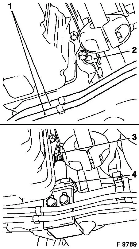
|
Remove, Disconnect Disconnect wiring harness plug (1) from oil temperature sensor and place cable aside - note cable routing. Disconnect wiring harness plugs from coolant temperature sender, coolant temperature sensor, fuel injection pump control unit, charge pressure sensor and crankshaft pulse pick-up. Detach cable connections from sheathed glow plugs. Detach front wiring trough (2) from cylinder head cover and upper part of intake manifold. Remove cable bundle bracket from engine transport shackles - place cable bundle with wiring trough and cable bundle bracket to rear. As of MY '98: Detach rear wiring trough from cylinder head cover. | 
|
Remove, Disconnect For X 20 DTL: Remove lower coolant hose from radiator - collect escaping coolant. Detach coolant hose (1) from alternator bracket (coolant flange). Release coolant hose (2) in direction of arrow and detach from heater core. Detach coolant hose (3) from coolant compensation tank. Detach coolant hose (4) from radiator. For X 20 DTL: Remove upper coolant hose (5) from thermostat housing and from radiator. | 
|
Remove, Disconnect Detach vacuum hose (1) from wastegate unit. Remove engine damping block bracket (2).
 Important! Important! With vehicles with airbag: turn steering wheel to straight ahead position, remove ignition key and engage steering lock.
Remove, Disconnect Remove clamp bolt for steering intermediate shaft (3) (interior). | 
|
Remove, Disconnect Detach both front wheels. Remove left and right wheel well panelling. Remove front panelling - see operation "Front Panelling, Remove and Install" in group "A". Detach swing arm (1) on both sides from spring strut support tube - counterhold with open-ended spanner at the two flattened surfaces. Remove axle shafts from wheel hubs (do not detach from transmission) - see operation "Axle Shafts, Remove and Install" in group "E". Remove/detach exhaust gas line heater element (2) downwards from auxiliary heater. Remove front exhaust pipe (3). | 
|
Remove, Disconnect Construct Base Frame KM-904 (2) with Centring Mount KM-905 (1) on hydraulic jack and place without clearance under front axle body (use hydraulic jack which can be lowered to at least 100 cm).
Important! Removal with pulse or impact screwdriver not permitted. Note different bolt lengths and washers. | 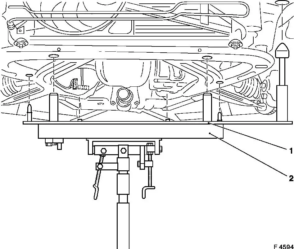
|
Notice: For clearer representation, illus. F8464 shows the front axle body without the hydraulic jack and centring mount.
Remove, Disconnect Remove fastening bolts (1) (4 off). Remove fastening bolts (2) (4 off). Remove fastening bolts (3) (2 off). Carefully lower front axle body with entire drive unit, steering gear and radiator - thereby ensuring that no attaching parts are damaged.
Important! Before installing the front axle body with drive unit: check thread of locking nuts (fastening bolts 1-3) for ease of movement, replace locking nuts if necessary - see operation " Replacement Locking Nuts" in group "A". | 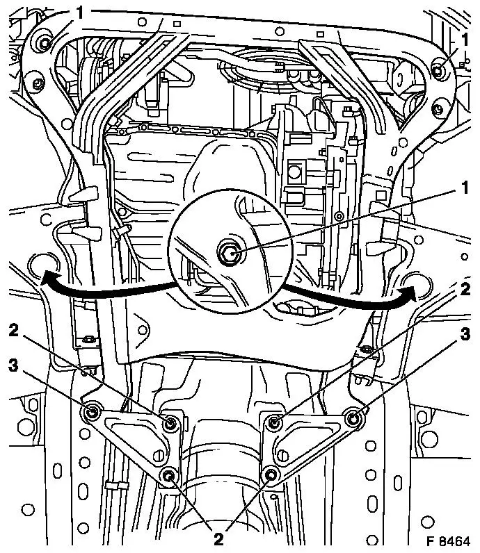
|
 Install, Connect Install, Connect Carefully insert front axle body with entire drive unit, steering gear and radiator in engine compartment and position free of play on chassis - use hydraulic jack, Base Frame KM-904 and Centring Mount KM-905. Thereby ensure that no attaching parts are damaged. Attach front axle body to chassis with new fastening bolts - note different bolt lengths (1 and 3: long bolts, 2: short bolts)
- tightening torque 100 Nm / 74 lbf. ft. + 45 ° + 15 ° 1) 2)
. Use torque wrench and KM-470-B.
Important! Installation with an impact screwdriver is not permitted. Note different bolt lengths and washers. |
|
1) Use new fastening bolts. 2) Insert fastening bolts with screw locking compound (red). The installation time including torque check is max. 5 min.
Install, Connect Connect front exhaust pipe to return manifold with new gasket and new fastening nuts - tightening torque 20 Nm / 15 lbf. ft. Connect front exhaust pipe to muffler - tightening torque 12 Nm / 9 lbf. ft. Attach exhaust gas line heater element to front axle body and heater element. Install axle shafts - see operation "Axle Shafts, Remove and Install" in group "E". Attach swing arms on both sides to spring strut support tube with new fastening nuts - counterhold with open-ended spanner at two flattened surfaces - tightening torque 65 Nm / 48 lbf. ft. Install front panelling - see operation "Front Panelling, Remove and Install" in group "A". Install left and right wheel well panelling. Attach wheels - tightening torque 110 Nm / 81 lbf. ft. Attach steering intermediate shaft to steering gear (interior) - tightening torque 22 Nm / 16 lbf. ft. + 45 ° + 15 ° 1) Attach engine damping block bracket to engine damping block and adapter - tightening torque 45 Nm / 33 lbf. ft. Connect vacuum hose to waste gate unit. Attach coolant hoses.
1) Re-cut thread for steering intermediate shaft before re-use. Insert new fastening bolts with screw locking compound (red). The installation time including torque check is max. 5 min.
Install, Connect Attach cable bundle bracket with cable bundle to engine transport shackles. Attach front wiring trough to cylinder head cover and upper part of intake manifold. Attach rear wiring trough to cylinder head cover. Attach all wiring connections which were connected to wiring trough or cable bundle - ensure cables are correctly routed.
Remove, Disconnect Detach KM-6173 from front axle body.
Install, Connect Clip hydraulic lines in brackets on front axle body. For version with automatic transmission: Clip selector lever actuating cable in counterpart and attach to selector lever actuating lever. For version with manual transmission: Attach pressure connection for hydraulic clutch actuator to manual transmission. For version with manual transmission (except F 23): Attach shift guide to shift rod - only tighten to specified torque after the transmission shift linkage has been adjusted.
Install, Connect For version with manual transmission (only F 23): Insert both shift cables into shift cable bracket and allow plastic clamps to engage. Attach shift cables to ball heads. Attach coolant lines. Connect multi-plug (rotary catch) and attach ground cable to body. Attach battery carrier to body and bracket to battery carrier. Fasten cable bundle to bracket and connect multiple plug (twist lock). Install battery and fasten fuse box and relay box to battery frame. Attach thermal insulation jacket to battery. Attach radiator with retaining brackets on both sides on air deflector panel. Attach vacuum hose to vacuum pump, switchover valve vacuum unit and exhaust gas recirculation valve - note routing. Connect brake servo vacuum line to vacuum pump - 18 Nm / 13 lbf. ft. Attach fuel lines to injection pump with new seal rings - tightening torque 15 Nm / 11 lbf. ft.
Install, Connect As of MY '98: Attach power steering pump fluid reservoir to fan housing. Notice: Before assembling components of the intake system (hoses, connections, etc.), they must be cleaned of any possible contamination (grease, oil, etc.). When tightening the hose clamps, be sure to observe exactly the tightening torque of 3.5 Nm / 2.6 lbf. ft.
Important! It is only ensured that the intake system is free of leaks, thus ensuring operational safety of the engine, if the hose clamps are tightened correctly to the prescribed tightening torque.
Install, Connect Attach charge air hose. Install air cleaner housing with air intake hose - see illustration "Air Cleaner Housing, Air Duct". As of MY '98: Attach relay box to air cleaner housing. Attach engine vent hose to cylinder head cover.
Install, Connect Connect wiring harness plug to hot film mass air flow meter. Up to MY '98: Connect wiring harness plug to intake air temperature sensor. Install engine cover and radiator cover. Connect battery electrically. Charge air conditioning - see operation "Air Conditioning, Evacuate and Charge" in group "D". Bleed clutch hydraulics - see operation "Clutch Hydraulics, Bleed" in group "K". Adjust transmission shift linkage - see operation "Transmission Shift Linkage, Adjust" in group "K". Top up cooling system - see operations "Cooling System, Top up and Bleed" and "Cooling System, Check for Leaks". Attach lower engine compartment cover.
Important! Bleed fuel system with KM-948 once it has been opened.
|
