
Corrado V6-2792cc 2.8L DOHC (1992)
Fuel Injector: Testing and Inspection
Checking Spray Pattern and Sealing
Checking injector spray pattern and sealing
- remove upper section of intake manifold (see Fuel Injectors, Removing/Installing)
- remove fuel rail assembly complete with fuel injectors
- disconnect harness connector from blue engine coolant temperature (ECT) sensor (G 62)
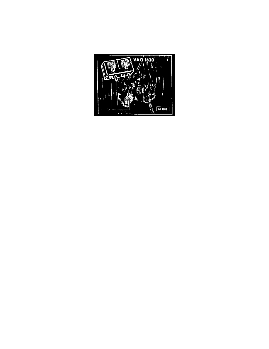
- preset digital potentiometer VAG 1630 to 15,000 Ohms
- connect the ECT harness connector to the VAG 1630 potentiometer using jumper wires from the VW 1594 adaptor kit
NOTE: If the VAG 1630 potentiometer is not available; use adaptor VAG 1490 by connecting the 15,000 Ohm side directly to the ECT harness
connector.
- fuel injectors remain electrically connected
- feed and return line remain connected to fuel rail
NOTE: There is a tool (VAG 1602) that can be used to measure the fuel quantity output of the fuel injectors, simultaneously. If a VAG 1602 is not
available, an acceptable method would be to substitute 6 separate beakers to collect the fuel and a single graduated beaker to measure each of the
accumulations individually.
- adjust location of measuring tubes in VAG 1602 to align with fuel injectors on fuel rail
- insert injectors into each of the VAG 1602 measuring tubes
- operate starter for several seconds and observe spray pattern
-
spray pattern must be the same for all injectors
- switch ON ignition for approx. 5 seconds and check for injector leakage
-
no more than 2 drops per injector is allowed
- empty VAG 1602 (or equivalent) of any residual fuel
NOTE: When installing the fuel injectors, be sure that the 0-rings in the fuel rail are not damaged. Always replace damaged 0-rings.
- activate DTC MEMORY (Fault memory) and then erase
-
any faults that are generated by checking the (G 62) ECT sensor will then be erased