volkswagen Workshop Repair Guides

Volkswagen Workshop Service and Repair Manuals

Checking DIS switch unit > < Vacuum unit leak test
34 PICT, Keihin carburettor and ignition system
Servicing TIC-H ignition system
Checking TCI-H ignition system

Note:

  • ◆ The specified values stated apply to an ambient temperature range of 0...+40 °C.
  • ◆ The tests are performance with the hand multimeter V.A.G 1526
Attention!
The respective measuring range is to be select before connecting up the test cables to prevent destruction of the electronic components.

Checking TCI-H switch unit -N41-

  • ● Ignition coil OK.

Engine code JB

 
V28-0382
  • ‒ → Pull plugs of DIS switch unit by pressing against surface on plug/switch -arrows- and connect together.

Continuation for all vehicles

  • ‒ Pull plug off TCI-H switch unit; to do so press wire clip.
 
V28-0713
  • ‒ → Use auxiliary leads from V.A.G 1594 to connect up hand multimeter V.A.G 1526 between contacts 2 and 4 on plug.
  • ‒ Switch on ignition.
         Specifications: approx. battery voltage.
  • ‒ If not, locate eliminate open circuit using CFD.
  • ‒ Switch off ignition.
  • ‒ Reconnect plug to TCI-H switch unit.
  • ‒ Pull plug of Hall sender (distributor).
 
U28-0010
  • ‒ → Use auxiliary leads from V.A.G 1594 to connect up hand multimeter V.A.G 1526 between terminal 1 (-) and terminal 15 (+) of ignition coil.
  • ‒ Switch on ignition.
    Specification: at least 2 volts; must drop off to 0 volts after 1...2 seconds.

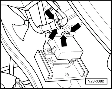
If not, renew TCI-H switch unit and check whether sealing compound has oozed out of ignition coil; if necessary, renew ignition coil as well.

  • ‒ Briefly connect centre wire of connector at distributor to earth.
    The voltage value indicated must briefly increase to at least 2 volts. If This is not the case, located and eliminated open circuit in centre wire/renew the switch unit.
  • ‒ Switch off ignition.
 
V28-0394
  • ‒ → Use auxiliary leads from V.A.G 1594 to connect hand multimeter V.A.G 1526 to outer contacts of plug of Hall sender (distributor).
  • ‒ Switch on ignition.
         Specifications: at 5 volts.

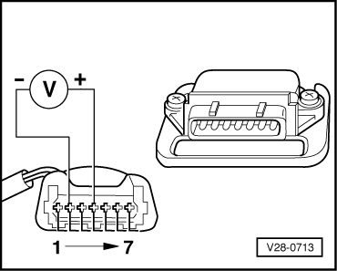
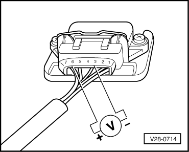
Note:

If the defect is present despite the specified values being obtained, the TCI-H switch unit should be renewed, or the open circuit between the plug of the Hall sender and the switch unit is to be located and eliminated.

Checking Hall sender

  • ● TCI-H switch unit OK.
  • ● Ignition coil OK.
  • ● Wire between TCI-H switch unit and distributor OK.
  • ● Connector and connection parts on distributor, Hall sender and TCI-H switch unit OK.
  • ‒ Pull high tension lead, terminal 4 out of distributor and earth it. Use auxiliary cable if necessary.
  • ‒ Detach rubber grommet from connector, TCI-H switch unit. Connector remains attached.
 
V28-0714
  • ‒ → Use auxiliary cables V.A.G 1594 to connect up hand multimeter V.A.G 1526 between contacts 3 and 6.
  • ‒ Switch on ignition.
  • ‒ Turn engine slowly by hand in direction of rotation and watch reading on the measuring instrument (hand multimeter).
         Specification: alternating between 0 and at least 2 V
  • ‒ If not, renew Hall sender.

Checking DIS switch unit > < Vacuum unit leak test