volkswagen Workshop Repair Guides

Volkswagen Workshop Service and Repair Manuals

Reworking valve seats > < Checking compression pressure
4 cyl. carburetor engine, mechanics (1.5, 1.6 and 1.8 litre engine)
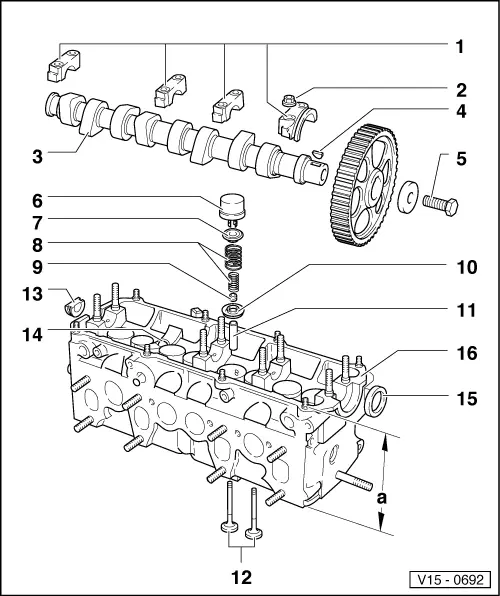
Servicing valve gear
 
V15-0692

Note:

Cylinder heads which have cracks between the valve seats or between a valve seat insert and the spark plug thread can continue to be used without reducing service life, provided that the cracks do not exceed a max. width of 0.5 mm or when no more than the first spark plug threads are cracked.

  • Bearing cap
    • ◆ With bearing cap 4 in the case of engines with no hydraulic bucket tappets
    • ◆ Pay attention to centre offset of bore => Fig. 2
    • ◆ Fit cap and determine position before installing camshaft
    • ◆ Installation sequence: removing and installing camshaft
 
V15-0692
  • 20 Nm
  • Camshaft
    • ◆ Checking axial clearance => Fig. 1
    • ◆ Removing and installing => page 15-26
    • ◆ Check radial clearance with Plastigage
      Wear limit: 0.1 mm
    • ◆ Runout: max. 0.01 mm
    • ◆ Identification and valve timing => Figs.3 and 4
  • Woodruff key
    • ◆ Ensure tight fit
  • 80 Nm
    • ◆ Counterhold with 3036 for loosening and tightening
 
V15-0692
  • Bucket tappet
    • ◆ Check axial clearance of camshaft before installing => Fig. 1
    • ◆ Oil contact surfaces
    • ◆ Do not interchange
    • Hydraulic bucket tappet:
    • ◆ Lay aside with contact surface facing downwards
    • ◆ Checking => page15-30
    • Bucket tappet with shim:
    • ◆ Checking and adjusting valve clearance => page 15-36
  • Upper valve spring retainer
    • ◆ Note version => Fig. 6
  • Upper valve spring
    Inner valve spring
    • ◆ Removing and installing
      Cylinder head removed: with 2037
      Cylinder head in situ:
      renewing valve stem oil seals => page 15-31
 
V15-0692
  • Valve stem oil seal
  • Lower valve spring retainer
    • ◆ Remove and install with 3047 A
  • Valve guide
    • ◆ Checking
    • ◆ Renewing => page 15-33
  • Valves
    • ◆ Valve dimensions =>Fig.5
    • ◆ Note version =>Fig. 6
    • ◆ Only grind in; do not rework
    • ◆ Checking and adjusting valve clearance
      ( not hydraulic bucket tappets)
  • Plug
    • ◆ Renew
  • Oil stop
    • ◆ Hydraulic bucket tappets only (4 bearing caps)
 
V15-0692
  • Oil seal
    • ◆ Lightly lubricate sealing lip and outer edge
    • ◆ Renewing
  • Cylinder head
    • ◆ Exchange cylinder heads with camshaft bearing shells => Fig. 7
    • ◆ Reworking valve seats => page15-23
    • ◆ Reworking dimension a = 132.6 mm (min. height)
    • ◆ Cracked cylinder head => note onpage 15-8
    • ◆ 1.6 l engine "big valve" cylinder head can be identified by casting number 1GS 103 373D
 
V15-0456

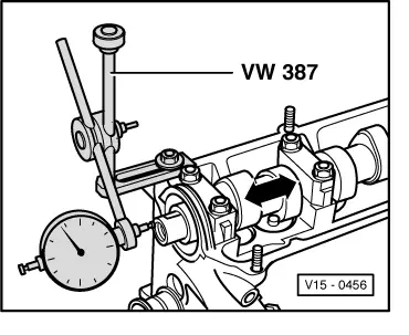
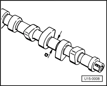
→ Fig.1     Checking axial clearance of camshaft

Wear limit: 0.15 mm

Measure with bucket tappets removed and first and last bearing caps installed.

 
V15-0098

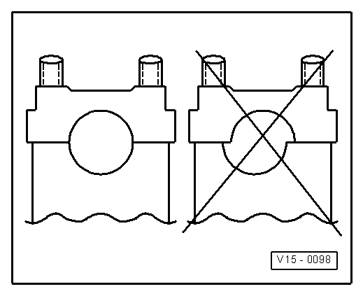
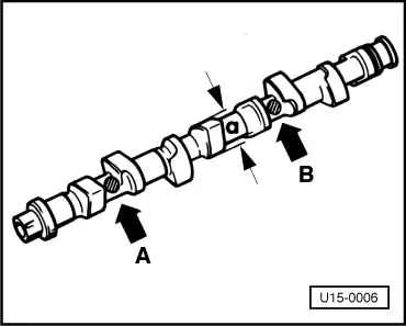
→ Fig.2     Installation position of camshaft bearing caps

Note centre offset. Before installing camshaft, mount bearing caps and determine installation position.

 
U15-0005

→ Fig.3     Camshaft identification, valve timing

Identification with adjustable bucket tappets

  • ◆ Cam base circle: a = dia. 38 mm

Engine codes

Lug on cam

Colour of paint between cams

1 (-A-)

3 (-B-)

1 + 2

3+4

EW ä07.85,

-

-

yellow

-

HN ä 07.85

EX ä09.83

x

-

blue

-

EX 10.85 ä 08.85

x

x

-

white1)

EX2)

x

x

-

-

EM, FN, FP, FR,

x

x

-

-

FV, GH, JB

FB, FD, FH, FK

x

-

-

-

FT3)

-

-

-

-

HM ä01.87

x

-

white1)

     1)     Not all camshafts are painted white

     2)     When performing repairs, camshaft with lug at 1st (-A-) and 3rd (-B-) cam and stamped-in code number "049J" (-C-) is to be replaced by a different version for engine code EX

     3)     Austria only (no identification)

Valve timing with 1 mm valve stroke

Engine codes

EM, FN, FP, FR, FV, GH, JB

EW ä 07.85,
HN ä 07.85,
GY 04.86 ä

Inlet opens

4° before TDC

5° before TDC

Inlet closes

46° after BDC

21°after BDC

Exhaust opens

44° before BDC

41° before BDC

Exhaust closes

6° after TDC

3° before TDC

Engine codes

EX ä 07.85, HM, HV

FB, FD, FH, FK

Inlet opens

1° before TDC

7° before TDC

Inlet closes

37° after BDC

43° after BDC

Exhaust opens

42° before BDC

47° before BDC

Exhaust closes

2° after TDC

3° before TDC

Engine codes

FT

Inlet opens

6° before TDC

Inlet closes

32° after BDC

Exhaust opens

42° before BDC

Exhaust closes

TDC

 
U15-0006

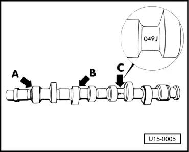
→ Fig.4     Camshaft identification, valve timing

Identification with hydraulic bucket tappets

  • ◆ Cam base circle: a = dia. 34 mm (with adjustable bucket tappets: a = dia. 38 mm)
  • ◆ Identification by way of stamped-in numbers and letters between inlet and exhaust cams

Engine codes

Cylinder 1

Cylinder 3

Arrow -A-

Arrow -B-

EW 08.85 ä

B/M

026

HN 08.85 ä

EX 08.85 ä

H/Q

026

EW 03.86 ä

HN 03.86 ä

M

026

RE 03.86 ä

EX 07.87 ä

Q

026

HM 02.87 ä

L

026

HV 02.87 ä

AJD 10.98 ä

L or AF

026

BBV 04.02 ä

L or AF

026

Valve timing with 1 mm valve stroke

Camshaft

-A-

-B-

-A-

-B-

B

026

M

026

Inlet opens

3° before TDC

TDC

Inlet closes

19° after BDC

22° after BDC

Exhaust opens

27° before BDC

28° before BDC

Exhaust closes

5° after

6° before TDC

Camshaft

-A-

-B-

-A-

-B-

H

026

Q

026

Inlet opens

3° before TDC

5° after TDC

Inlet closes

33° after BDC

41° after BDC

Exhaust opens

41° before BDC

37° before BDC

Exhaust closes

5° after

1° before TDC

Camshaft

-A-

-B-

L or AF

026

Inlet opens

8° after TDC

Inlet closes

44° after BDC

Exhaust opens

34° after BDC

Exhaust closes

2° after

 
V15-0024

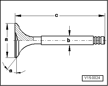
→ Fig.5     Valve dimensions

Note:

Valves are not to be reworked. Only grinding is permitted.

Engine codes

EM,

FB,

FD,

FH,

FK,

FN,

FP,

FR,

FT,

FV,

GH,

JB,

GY,

HM

Inlet valve

Exhaust valve

a

34.00 mm

31.00 mm

b

7.97 mm
7 mm1)

7.95 mm
7 mm1)

c

98.70 - 0.50 mm

98.50 - 0.50 mm

alpha

45°

45°

     1)     Engine codes HM ä 01.97 only

 
V15-0024

Engine code

AJD

BBV

Inlet valve

Exhaust valve

a

38.00 mm

33.00 mm

b

7.97 mm

7.97 mm

c

91.90 - 0.90 mm

91.20 - 0.40 mm

alpha

45°

45°

Engine codes

EW ä 07.85,

EX ä 07.85,

HN ä 07.85

Inlet valve

Exhaust valve

a

38.00 mm

33.00 mm

b

7.97 mm

7.95 mm

c

98.70 - 0.50 mm

98.50 - 0.50 mm

alpha

45°

45°

Engine codes

EW 08.85 ä,

EX 08.85 ä,

HN 08.85 ä,

RE

(with hydraulic valve clearance compensation)

Inlet valve

Exhaust valve

a

38.00 mm

33.00 mm

b

7.97 mm

7.95 mm

c

91.90 - 0.90 mm

91.20 - 0.40 mm

alpha

45°

45°

 
U15-0007

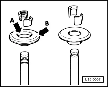
→ Fig.6     Valve types

05.81 ä installation of valves with 3 grooves

Distinguishing features

  • ◆ Valve with 3 grooves on stem (previously one groove)
  • ◆ Valve taper with 3 beads (previously one bead)
  • ◆ Valve spring seat:
  • Surface copper-plated or yellow chromation (previously steel grey) with approx. 1.5 mm inner chamfer -arrow A- (previously no chamfer) and broad outer chamfer -arrow B-

Note:

When performing repairs, 1 and 3-groove valves can be mixed. It is to be noted that the respective valves are only to be installed with the envisaged valve tapers and valve spring seats.

 
U15-0008

→ Fig.7     Exchange cylinder heads with camshaft bearing shells

Exchange cylinder heads/exchange engines are sometimes supplied with bearing shells for camshafts.

  • ◆ Cylinder head with standard size camshaft
    a = 26.00 mm dia.
  • ◆ Cylinder head with undersize camshaft
    a = 25.75 mm dia. and dot of yellow paint on VW-Audi emblem

Note:

Undersize camshafts are not supplied as replacements. For repairs, install a standard size camshaft with corresponding bearing shells.

Reworking valve seats > < Checking compression pressure