volkswagen Workshop Repair Guides

Volkswagen Workshop Service and Repair Manuals

Checking DIS switch unit > < Checking ignition timing control
K-Jetronic/Ignition system
Safety measures for TCI-H system
Checking TCI-H switch unit and Hall sender

Checking with TCI tester V.A.G 1451

  • ‒ Carry out test per tester operating instructions.

Checking with hand multimeter V.A.G 1526 and auxiliary leads from V.A.G 1594

Notes:

  • ◆ The specifications given are valid for an ambient temperature of 0...+40°C.
  • ◆ If the measured values deviate from the specification, check wiring for open circuit in accordance with current flow diagram before replacing components.
Attention!
To prevent destruction of the electronic components, switch multimeter to voltage range V = each time before connecting the taster leads.

A - Checking TCI-H switch unit -N41-

 
V28-0263

Ignition coil OK, checking =>page 28-25

On engines with DIS

  • ‒ → Pull plugs off DIS switch unit and connect together.
  • ‒ Pull plug of TCI-H switch unit -N41-; to do so press wire clip.
 
V28-0713
  • ‒ → Connect hand multimeter with auxiliary cables between contacts -4- and -2- on connector.
  • ‒ Switch on ignition.
         Specification: Approx. battery voltage

Otherwise locate open circuit with aid current flow diagram, and rectify:

=> Current flow diagrams, Electrical fault finding and Fitting locations

  • ‒ Switch off ignition.
  • ‒ Re-connect plug to TCI-H switch unit.
  • ‒ Pull plug off Hall sender (distributor); to do so pres wire clip.
 
V28-0730
  • ‒ → Connect hand multimeter with auxiliary cables between 1 (-) and terminal 15(+) on ignition coil.
  • ‒ Switch ignition on.
         Specification:
         At least 2 volts. must drop 0 after approx.1...2 seconds.

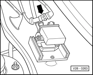
Otherwise renew TCI-H switch unit and check whether sealing compound has escaped from the ignition coil. If necessary, renew ignition coil as well.

  • ‒ Briefly earth centre wire of distributor connector. The indicated voltage must rise briefly to at least 2 V.
    Otherwise, locate open circuit in centre wire and eliminate/renew TCI-H switch unit.
  • ‒ Switch off ignition.
 
V28-0394
  • ‒ → Connect hand multimeter with auxiliary cables to outer contacts of Hall sender connector (distributor).
  • ‒ Switch on ignition: at least 5 volt

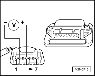
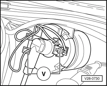
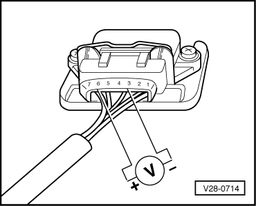
Note:

If the fault still exist although the specifications are obtained, the TCI-H switch unit should be sender connector and switch unit located and rectified.

B - Checking Hall sender -G40-

  • ● TCI-H switch unit OK.
  • ● Ignition coil OK.
  • ● Wire between TCI-H switch unit and distributor OK.
  • ● Connector and connecting elements at distributor, Hall sender and TCI-H switch OK.
  • ● On engines with DIS:
    • ‒ Pull cable out of terminal 4 on distributor and earth it using an auxiliary cable from V.A.G 1594.
 
V28-0714
  • ‒ → Connect hand multimeter with auxiliary cables from V.A.G1594 Between contact 6 and 3 of attached connector for TCI-H switch unit.
  • ‒ Switch on ignition.
  • ‒ Turn engine slow by hand in normal direction or rotation and watch reading on tester.
         Specification: Alternating between 0 and min. 2 volts.

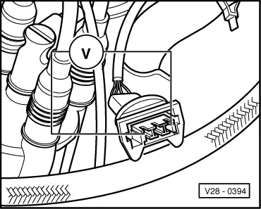
If not replace Hall sender -G40-.

Checking DIS switch unit > < Checking ignition timing control