
Removing and Installing Brake Pedal & Master Cylinder
| Removing and installing brake pedal/brake servo and brake master cylinder |
 Note
Note| t | The brake pedal travel must not be restricted by additional floor coverings. |
| t | Grease all bearing points with grease -G 000 602- before installing. |
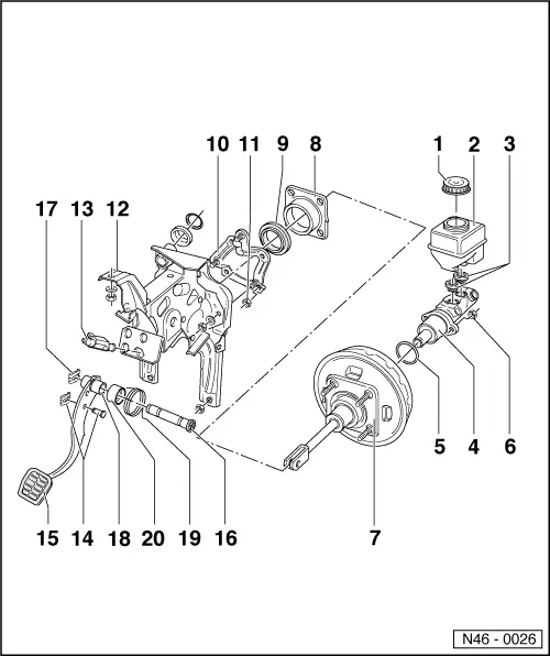
| 1 - | Cover |
| q | Contact pin in cover in vehicles with brake fluid warning indicator. |
| q | Function check: Press contact pin in with ignition switched on and handbrake released, warning lamp must light up. |
| 2 - | Brake fluid reservoir |
| 3 - | Sealing plug |
| q | Moisten with brake fluid and press into expansion tank. |
| 4 - | Brake master cylinder, Ø 20.64 mm |
| q | Cannot be repaired. |
| q | If faulty renew complete. |
| 5 - | Oil seal |
| q | Renew. |
| 6 - | Hexagon nut, 20 Nm |
| 7 - | Brake servo (7”) |
| q | 9" in vehicles with automatic gearbox. |
| q | If faulty, renew complete. The vacuum required is taken from the intake manifold. On diesel engines an exhauster is installed to generate vacuum. |
| 8 - | Mounting bracket |
| q | For brake servo. |
| 9 - | Gasket |
| q | For brake servo. |
| 10 - | Mounting bracket |
| 11 - | Hexagon nut, 20 Nm |
| 12 - | Mounting bracket |
| q | For pedal cluster. |
| 13 - | Brake light switch |
| q | Before installing pull plunger out fully from switch. |
| q | Guide switch through fitting hole and secure by turning 90° to the right |
| 14 - | Pin with retainer |
| 15 - | Brake pedal |
| 16 - | Axis for brake and clutch pedals |
| 17 - | Retaining ring |
| q | Ensure secure seating. |
| 18 - | Bearing bush |
| 19 - | Return spring |
| q | For brake pedal. |
| 20 - | Bearing tube |
| q | For return spring. |