volkswagen Workshop Repair Guides

Volkswagen Workshop Service and Repair Manuals

Dismantling and assembling 1st to 3rd gear clutch -K1- with turbine shaft on gearboxes from 01.93 > < Dismantling and assembling free wheel with -B1- piston
Automatic gearbox 096
Dismantling and assembling 1st to 3rd gear clutch -K1- with turbine shaft on gearboxes up to 12.92
 
V38-0689

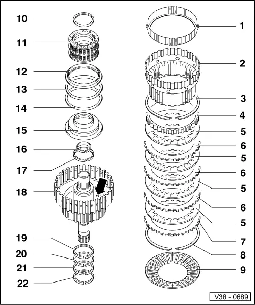
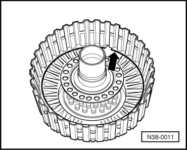
Gearboxes up to 12.92

Note:

When performing repairs to the clutch, ensure that the ball valve (arrow) is not damaged.

  • Supporting ring
    • ◆ 4-piece, unclip from inner plate carrier
    • ◆ Inserting =>Fig. 4
  • Inner plate carrier
    • ◆ Inserting =>Fig. 6
    • ◆ Assembling =>Fig. 4
  • Circlip
    • ◆ Different thicknesses
    • ◆ Mark after removing and insert in same position
 
V38-0689
  • Thrust plate
    • ◆ Smooth side faces inner plate
    • ◆ Insert together with inner plate carrier => Fig. 4
  • Inner plate
    • ◆ Quantity=> Page 00-3
    • ◆ Insert together with inner plate carrier => Fig. 4
  • Outer plate
    • ◆ Quantity=> Page 00-3
    • ◆ Insert together with inner plate carrier => Fig. 4
  • Thrust plate
    • ◆ Curved side to diaphragm spring
    • ◆ Installing=> Fig. 5
  • Circlip
    • ◆ Installing=> Fig. 3
  • Diaphragm spring
    • ◆ Insert with curved side to piston
 
V38-0689
  • Circlip
    • ◆ Removing and installing =>Fig. 2
  • Intermediate spring ring
    • ◆ With spring supporting shell and compression springs
  • Operating ring
    • ◆ Insert with rounded surface facing intermediate spring ring
  • Disc spring
    • ◆ Curved side faces operating ring
    • ◆ Installation position =>Fig.1
  • Disc spring
    • ◆ Curved side faces operating ring
    • ◆ Installation position =>Fig.1
 
V38-0689
  • Piston
    • ◆ Sealing lips are vulcanised to piston
    • ◆ Moisten sealing lips with ATF before installing
    • ◆ Turn piston slightly when installing
  • Piston ring (small ø)
    • ◆ Check that it is correctly located
      => Fig. 7
    • ◆ Fitting => Fig. 8
  • Piston ring
    • ◆ Check that it is correctly located
      => Fig. 7
    • ◆ Fitting => Fig. 8
  • Clutch housing with turbine shaft
    • ◆ Check bearing bushes. Replace housing if bushes are damaged.
    • ◆ Before inserting the inner plate carrier insert diaphragm spring (item 9), circlip (item 3) and one inner and outer plate in the clutch housing =>Fig. 5
 
V38-0689
  • Piston ring
    • ◆ Check that it is correctly located
      => Fig. 7
    • ◆ Fitting => Fig. 8
  • Piston ring
    • ◆ Check that it is correctly located
      => Fig. 7
    • ◆ Fitting => Fig. 8
  • Piston ring
    • ◆ Check that it is correctly located
      => Fig. 7
    • ◆ Fitting => Fig. 8
  • Piston ring
    • ◆ Check that it is correctly located
      => Fig. 7
    • ◆ Fitting => Fig. 8
 
V38-0698

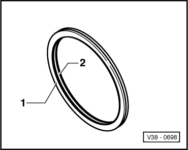
→ Fig.1    Installation position of disc springs

  • ‒ Install disc springs -1- and -2- so that when placed together the outer edges touch. There is a clearance at the inner diameter.
 
V38-0699

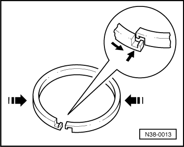
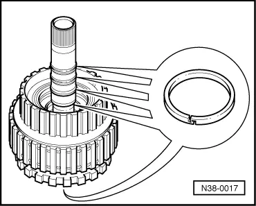
→ Fig.2    Removing and installing circlip

  • ‒ Press intermediate spring ring down far enough for the circlip (arrow) to be inserted in the groove.
 
N38-0011

→ Fig.3    Inserting circlip

  • ‒ Insert circlip (arrow) in the groove, diaphragm spring is slightly pretensioned.
 
V38-0701

→ Fig.4    Placing inner and outer plates on inner plate carrier and clipping in support ring

  • ‒ Insert the thrust plate and the inner and outer plates and then clip supporting ring (arrow) in place.

Note:

An inner and an outer plate must be placed in the clutch housing before inserting the inner plate carrier.

 
V38-0702

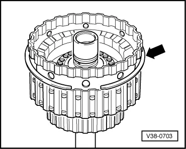
→ Fig.5    Inserting pressure plate, first inner and first outer plate into clutch housing

 
V38-0703

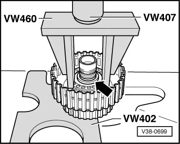
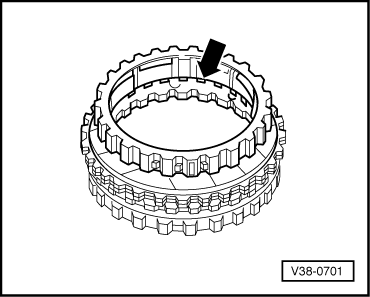
→ Fig.6    Inserting inner plate carrier and installing circlip (arrow)

  • ‒ Lift inner plate carrier slightly to install circlip.
 
N38-0017

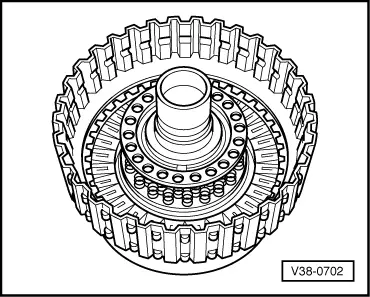
→ Fig.7    Checking seating of piston rings

There are two piston rings installed on the turbine shaft inside the clutch housing.

  • ‒ Ensure that the ends of the piston rings are hooked together.
 
N38-0013

→ Fig.8    Fitting and hooking ends of piston ring together

  • ‒ Place piston ring in groove.
  • ‒ To hook ends together press sides of ring in and guide ends over one another.
  • ‒ Do not twist piston ring out of groove on one side.

Dismantling and assembling 1st to 3rd gear clutch -K1- with turbine shaft on gearboxes from 01.93 > < Dismantling and assembling free wheel with -B1- piston