volkswagen Workshop Repair Guides

Volkswagen Workshop Service and Repair Manuals

Checking and adjusting end position of installed temperature flap positioning motor > < Servicing Climatronic - Passenger compartment
Heating, Air conditioning
Climatronic - Air conditioner with automatic regulation (R134a refrigerant)
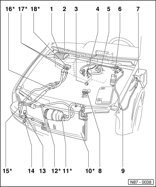
Servicing Climatronic - engine compartment
 
N87-0038

Note:

Parts marked with an * can only be serviced by specially equipped service workshops, as refrigerant must be evacuated with Service station V.A.G 1885.

  • Dust and pollen filter
    • ◆ Removing => Page 80-1, item-4-
  • Plenum chamber cover
    • ◆ Removing and installing => Page 80-1, item-3-
  • Water drain valve
    • ◆ Behind bulkhead insulation
    • ◆ Removing and installing ; Fig. 2
 
N87-0038
  • Coolant temperature sender -G62-
    • ◆ Only vehicles up to 07.95
    • ◆ Checking: self diagnosis using V.A.G 1551
    • ◆ Task: coolant temperature sender controls air distribution defrost/footwell and fresh air blower speed depending on temperature
    • ◆ In event of -G62- failure : operation continues assuming a value of +125°C
    • ◆ Removing and installing on vehicles with engine code ABF => Fig. 1
 
N87-0038
  • Heat exchanger and vacuum hose guide
  • Radiator fan control unit -J293-
    • ◆ Note Part No.
  • Vacuum reservoir
    • ◆ Insertion depth for vacuum hose: 30 mm
    • ◆ Removing and installing => Page 87-56 ; Fig.5
 
N87-0038
  • Thermo switch for air conditioner cut-off -F163- and thermo switch for coolant fan, 3rd speed -F165-
    • ◆ Thermo switch for air conditioner cut-off -F163- only on vehicles with engine codes AAA or ABF
    • ◆ Thermo switch for coolant fan, 3rd speed -F165- only on vehicles with 3-speed fan motor
    • ◆ -F165- switch coolant fan: into 3rd speed as temperature increases (on at 112°C, off at 108°C).
    • ◆ -F163- switches off magnetic coupling -N25- at excessively high coolant temperature (off at 119°C, on at 112°C).
    • ◆ Removing and installing on vehicles with engine code ABF => Fig. 1
    • ◆ Removing and installing on vehicles with engine code AAA => Page 87-56 ; Fig.3
 
N87-0038
  • Vacuum hose
    • ◆ Vacuum hose connection diagram => Page 87-128
  • Condenser*
  • Pressure relief valve*
  • Magnetic coupling -N25-*
    • ◆ Checking: self diagnosis using V.A.G 1551 (current path to magnetic coupling checked)
  • Air conditioner pressure switch -F129-
    • ◆ Checking: self diagnosis using V.A.G 1551
    • ◆ Removing and installing:
    • ‒ Tightening torque 8 Nm
    • ‒ Renew O ring seal (note Part No.).
 
N87-0038
  • Ambient temperature sensor -G17-
    • ◆ Function: temperature sensor controls temperature flap and fresh air blower, depending on temperature
    • ◆ In event of failure: fresh air intake duct temperature sensor -G89- takes over task. If both sensors are defective, operation continues assuming a value of +10°C. Air recirculation not possible. Control and display unit -E87- indicates: "--"
    • ◆ Vehicles up to 07.95:
      Removing and installing => Fig. 2
    • ◆ Vehicles from 08.95:
      Removing and installing => Fig. 3
    • ◆ Checking: self diagnosis using V.A.G 1551
 
N87-0038
  • Fluid reservoir with drier*
  • Sight glass*
  • Evacuating and charging valve*
  • Expansion valve*
    • ◆ Checking insulation piece for expansion valve => Page 87-56 ; Fig.1
 
N87-0078

→ Fig.1     Removing and installing coolant temperature sender -G62- and air conditioner cut-off thermo switch -F163- on vehicles with engine code ABF

Notes:

  • ◆ Cooling system is pressurized when engine is warm. If necessary, release pressure before carrying out repairs.
  • ◆ Refill with coolant after installing thermo-switch.
  •      1 -     Clip
  •      2 -     Connection
  •      3 -     O ring
  •      4 -     Coolant temperature sender -G62-/air conditioner cut-off thermo switch -F163-
 
V87-1445

→ Fig.2     Removing and installing ambient temperature switch -G17-

(Vehicles up to 07.95)

  •      1 -     Hexagon bolt, M8
    • Torque setting 15 Nm
  •      2 -     Temperature sensor retainer
  •      3 -     Horn bracket
  •      4 -     Plastic clip
  •      5 -     Ambient temperature sensor
  •      6 -     Horn
 
N87-0178

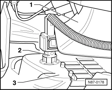
→ Fig.3     Removing and installing ambient temperature switch -G17-

(Vehicles from 08.95)

  •      1 -     Horn
  •      2 -     Ambient temperature sensor
  •      3 -     Cover

Checking and adjusting end position of installed temperature flap positioning motor > < Servicing Climatronic - Passenger compartment